skoda Workshop Repair Guides

Skoda Workshop Service and Repair Manuals

Repairing front axle > < Front axle - Overview of the repair chapters
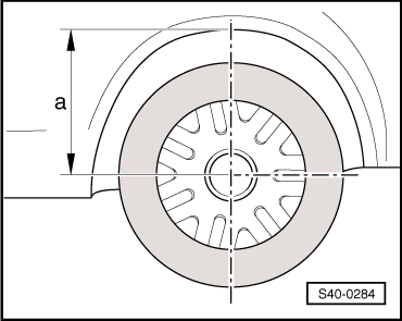
Raise the wheel-bearing housing in the rebound state (unladen weight position)
Special tools and workshop equipment required
t  Engine/gearbox jack, e.g. -V.A.G 1383/A-
t  Tensioning strap -T10038-
t  Support -T10149-
  Note
All screws must always be tightened firmly in the unladen condition (unladen weight position) to the chassis parts with rubber-metal bearings - do not load the vehicle!
Unladen weight:
Weight of the vehicle with full fuel tank and full water reservoir for windscreen wiper/washer and headlamp cleaning system, spare wheel, tool kit, jack and without driver. The spare wheel, tool kit and jack must be located in the position prescribed by the vehicle manufacturer.
Rubber metal bearings have a limited slewing range.
Therefore the axle components with rubber-metal bearings must be put in a position before tightening, which corresponds to the position while driving.
Otherwise the rubber-metal bearing will be under tension and as a result, will have a lower life.
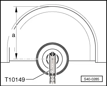
This position on the lift platform can be simulated by lifting out the corresponding wheel-bearing housing with the engine/gearbox jack e. g. -V.A.G 1383/A- and the support -T10149-.
   
–  Before commencing work, measure e.g with a measuring tape, the dimension -a- from wheel centre to lower edge of the wheelhouse.
Measuring must be performed when the vehicle is on the ground and in the unladen condition (unladen weight position) - do not load the vehicle.
–  Note the measured value. It is required when tightening the screws to the chassis parts with rubber-metal bearings.
Before the corresponding wheel-bearing housing is lifted, the vehicle must be lashed securely at the supporting arms of the lift platform with the tensioning straps -T10038-.
  WARNING
If the vehicle is not lashed, there is a risk of the vehicle toppling off the lift platform.
–  Remove wheel.
–  Rotate the wheel hub until one of the holes for the wheel bolts is located at the top.
–  Install support -T10149- with wheel bolt at the wheel hub.
  S40-0284
The tightening of the corresponding screw must only be performed, if the measured dimension -a- between the wheel hub centre and the lower edge of the wheel house is achieved before commencing work.
–  Raise up the wheel-bearing housing using the engine/gearbox jack e. g. -V.A.G 1383/A- until dimension -a- is achieved.
  WARNING
t  Do not raise or lower the vehicle, if the engine/gearbox jack is positioned under the vehicle.
t  Do not leave the engine/gearbox jack e. g. -V.A.G 1383/A- positioned under the vehicle for longer than necessary.
–  Tighten up the corresponding screws fully to the specified tightening torque.
–  Lower the wheel bearing housing.
–  Pull out the engine/gearbox jack e.g. -V.A.G 1383/A- from underneath the vehicle.
–  Remove support -T10149-.
–  Remove tensioning strap -T10038-.
  S40-0285

Repairing front axle > < Front axle - Overview of the repair chapters