skoda Workshop Repair Guides

Skoda Workshop Service and Repair Manuals

Removing and installing the track control arm > < Removing and installing the steering joint
Release assembly carrier in the service position and align
Special tools and workshop equipment required
t  Engine/gearbox jack with adapter, e.g. - V.A.G 1383 A- with -V.A.G 1359/2-
t  Wooden insert 490 x 270 x 50 mm for adapter -V.A.G 1359/2-
t  Fixing device -T 10096-
Release the assembly carrier and align - remove:
  Caution
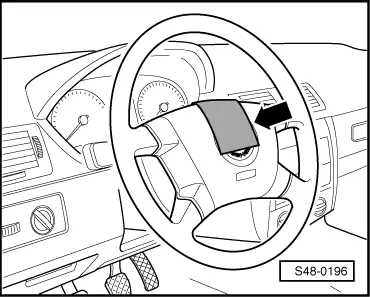
Bring the steering wheel in its central position (with the wheels straight ahead) and make sure that it does not turn during repairs as this could damage the coil spring of the airbag unit.
   
–  Secure the steering wheel with the wheels in straight ahead position with adhesive tape -arrow- against unintended turning.
  S48-0196
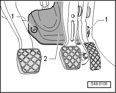
–  Unscrew plastic nuts -1-.
–  Unclip cover -2-.
  S48-0106
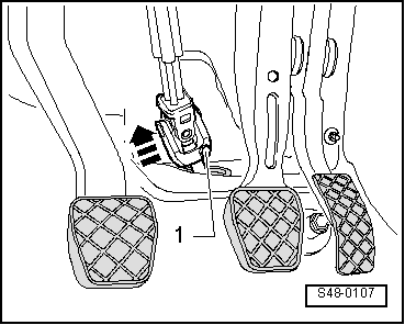
–  Release screw -1-.
–  Remove universal joint (in the -direction of the arrow-) from the input shaft of the power-steering gear.
–  Remove the sound dampening system → Body Work; Rep. gr.50.
Vehicles with the exhaust system below the assembly carrier
–  Remove pre-exhaust pipe → Engine; Rep. gr.26.
  S48-0107
Continued for all vehicles
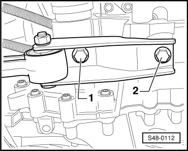
–  Release screws -1- and -2- of pendulum support.
  S48-0112
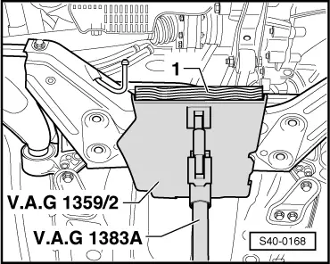
–  Insert wooden insert-1- in the adapter, e.g. - V.A.G 1359/2-.
–  Support the assembly carrier with engine/gearbox jack with adapter.
  Note
t  Note the following work steps and absolutely ensure that you follow the sequence.
t  The fixing bolts for -T10096- must only be tightened to maximum 20 Nm as otherwise the fixing bolt thread becomes damaged.
  S40-0168
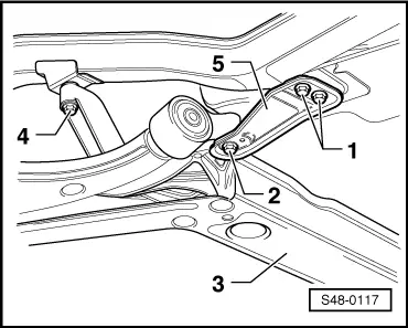
–  Unscrew left screw -4- for assembly carrier -3-, screw in a fixing bolt of - T10096- and tighten to 20 Nm.
–  Unscrew right screw -4- for assembly carrier (not shown in figure), screw in fixing bolt of - T10096- and tighten to 20 Nm.
–  Unscrew bolts -1- on both sides.
–  Unscrew the left screw -2- and remove support -5-.
–  Screw in fixing bolts of -T10096 - and tighten to 20 Nm.
–  Unscrew the right screw -2- and remove support -5-.
–  Screw in fixing bolts of -T10096 - and tighten to 20 Nm.
The fixing of the assembly carrier is completed once all 4 screws (Pos. -2- and -4- on both vehicle sides) are consecutively replaced with the fixing bolts.
  S48-0117
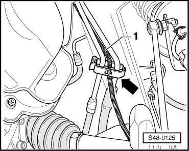
–  Release pressure line, return line and the line of the power-steering sensor -G250- from the spacer holder -arrow-.
  Note
When lowering the assembly carrier make sure that the pressure line, return hose and the line of the power-assisted steering sensor -G250- are not exposed to traction.
–  Lower assembly carrier approx. 4 cm and through this slacken from the fixing bolts.
  Note
When lowering the assembly carrier make sure there is sufficient clearance between the drive shafts and the stabilizer.
–  Slowly lower the assembly carrier with engine/gearbox jack and with adapter.
Tighten assembly carrier - install:
–  Raise assembly carrier until the consoles touch both sides of the body.
  S48-0125
–  Insert pressure line, return line and the line of the power-steering sensor -G250- into the spacer holder -arrow- and close the holder.
  Note
t  Note the following work steps and absolutely ensure that you follow the sequence.
t  Unscrew the fixing bolts of -T10096- one at a time. It should be subsequently replaced by a new bolt tightened to the recommended torque.
  S48-0125
–  Unscrew fixing bolt -1- of -T10096- from the left, screw in new bolt and tighten to the recommended tightening torque.
3 - Assembly carrier
–  Unscrew fixing bolt -1- of -T10096- from the right (shown in figure), screw in new bolt and tighten to the recommended tightening torque.
–  Unscrew fixing bolt -2- of -T10096- from the left.
–  Install left support.
–  Screw in new bolts for the left support and tighten at the rear by hand.
–  Screw in new bolt for left console and support and tighten to the recommended tightening torque.
–  Tighten the rear left support bolts to the recommended tightening torque.
–  Unscrew right fixing bolts -2- of -T10096- (shown in figure).
–  Install right support.
–  Screw in new bolts for the right support and tighten at the rear by hand.
–  Screw in new bolt for right console and support and tighten to the recommended tightening torque.
–  Tighten up the rear right support bolts to the recommended tightening torque.
–  Remove engine/gearbox jack with adapter.
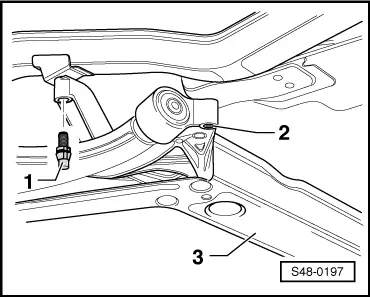
  S48-0197
–  Mount pendulum support on the gearbox and tighten new screws -1- and -2-.
  Note
Position the screws -1- in the elongated holes of the pendulum support in such a way that there is maximum distance between the gearbox and the assembly carrier.
Vehicles with the exhaust system below the assembly carrier
–  Install front exhaust pipe → Engine; Rep. gr.26.
Continued for all vehicles
–  Install the noise insulation → Body Work; Rep. gr.50.
  S48-0112
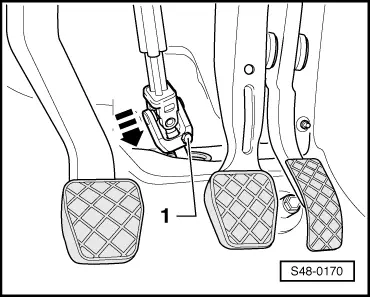
–  Slide the universal joint of the steering column in the -direction of the arrow- onto the input shaft of the power steering and tighten with a new screw -1-.
  S48-0170
–  Fit cover -2- with plastic nuts -1-.
–  Remove the securing mechanism which prevents the steering wheel from turning (adhesive tape).
  Note
It is necessary to perform a vehicle alignment in the event of → Chapter.
–  Perform a test drive.
  Caution
If after the test drive and with the front wheels pointing straight ahead the steering wheel is off straight, perform a chassis alignment → Chapter.
  S48-0106
Tightening torques:
Console to body
t  Use new screws!
70 Nm + 90°
Support to body
t  Use new screws!
20 Nm + 90°
Pendulum support to gearbox
t  Use new screws!
30 Nm + 90°
Fixing bolt of -T10096-20 Nm


Removing and installing the track control arm > < Removing and installing the steering joint