skoda Workshop Repair Guides

Skoda Workshop Service and Repair Manuals

Rear axle with disc brake > < Replacing the rubber-metal bearing - version 1
Replacing the rubber-metal bearing - version 2
Special tools and workshop equipment required
t  Assembly device -MP5-400/1-
t  Assembly device -MP5-400/2-
t  Assembly device -MP5-400/3-
t  Assembly device (nut) -T10254/4-
t  Assembly device (screw) -T10254/5-
t  Pipe -T10263/6-
t  Hydraulic cylinder -VAS 6178-
t  Foot pump -VAS 6179-
t  Tensioning strap -T10038-
t  Engine/gearbox jack with adapter, e.g. -V.A.G. 1383/A- with -V.A.G. 1359/2-
Removing:
–  Raise vehicle and remove rear wheels.
   
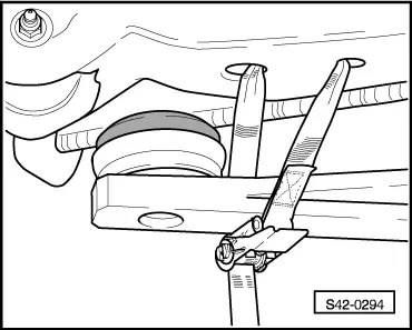
Before the rear axle is removed, the vehicle must be lashed at the supporting arms of the lift platform with the tensioning straps -T10038-.
  WARNING
If the vehicle is not lashed, there is a risk of the vehicle toppling off the lift platform.
–  Unscrew screws of front wheelhouse liners on both vehicle sides → Body Work; Rep. gr.66.
  S42-0294
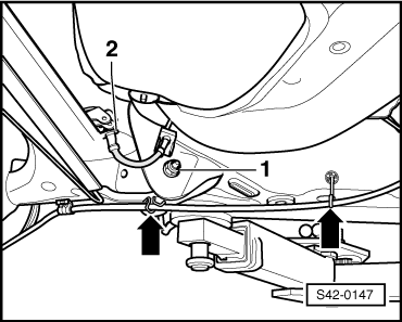
–  Unhook handbrake cable from the holders -arrows- (on both vehicle sides).
  S42-0147
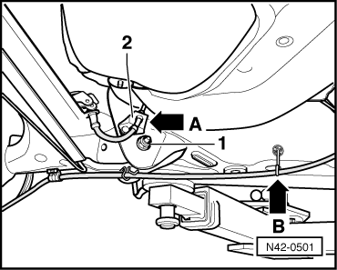
–  Slacken the brake line holder -2- from the vehicle body, on no account separate on the left -arrow A-.
–  Unhook the brake line from the right holders, on no account separate.
Only on vehicles equipped with an Xenon headlights
–  Disconnect the tension rod for the sender at the rear of the assembky carrier → Electrical System; Rep. gr.94.
Vehicles with ABS
–  Unhook the ABS line from the clips.
  N42-0501
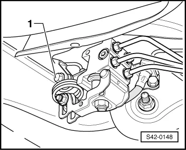
Vehicles fitted with load-sensitive brake pressure regulator (vehicles without ABS)
–  Release screw -1-.
  S42-0148
Continued for all vehicles
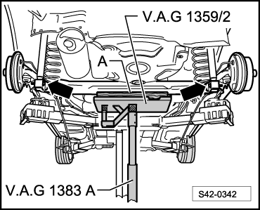
–  Insert wooden block -A- into the adapter, e.g. -V.A.G 1359/2-.
–  Support the axle with engine/gearbox jack with adapter.
  S42-0342
–  Unscrew the nuts of the fixing screws -1- from the axle.
–  Remove fixing screws -1- from the axle.
–  Lower the rear axle out of the bearing brackets so that the brake line is not damaged.
–  Secure axle e.g with wire to body.
  S42-0147
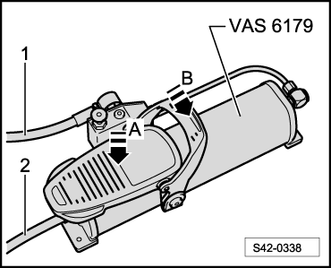
–  Connect hydraulic line -1- of hydraulic pump -VAS 6179- with quick coupling to hydraulic cylinder -VAS 6178-.
–  Connect compressed air supply -2- with quick coupling to hydraulic pump -VAS 6179-.
  S42-0338
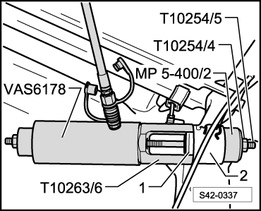
–  Position assembly devices, as shown, screw together and counterhold by hand.
  Note
  S42-0337
t  The pipe -T10263/6- must be installed on the rubber-metal bearing in such a way that the contact surface of the pipe -1- rests evenly against the rubber-metal bearing.
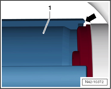
t  Cut off the rubber edge in the contact point e.g with a sharp knife so that the pipe cutout -arrow- rests fully on the plastic shoulder/rubber-metal bearing.
t  When pulling out the rubber-metal bearing, the plastic shoulder/rubber-metal bearing breaks off. In case of breakage, a loud crack can be heard.
  N42-10372
–  Carefully depress the pedal of the hydraulic pump -VAS 6179--arrow A-.
The hydraulic cylinder -VAS 6178- is therefore activated.
  S42-0338
–  Pull the rubber-metal bearing -1- out of the axle body -2-.
–  Counterhold the assembly devices by hand when completing the pull-out process.
  S42-0337
–  Carefully depress the pedal of the hydraulic pump -VAS 6179--arrow B-.
While doing so, the hydraulic cylinder -VAS 6178- returns to the initial position.
–  Remove assembly devices and unscrew assembly device (nut) -T10254/4-.
  S42-0338
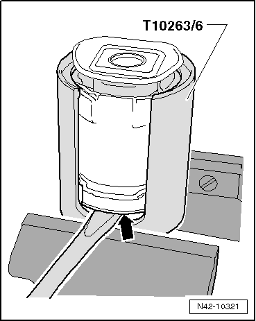
–  Clamp the pipe -T10263/6- in the vice, as shown in the fig.
–  Remove the rubber-metal bearing from the pipe -T10263/6-, for example using a screwdriver, drive out with a hammer if necessary.
  N42-10321
Installing:
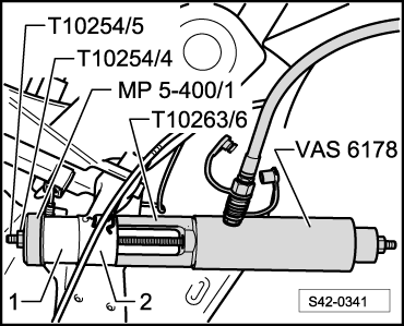
–  Position assembly devices, as shown, screw together and counterhold by hand.
1 - Rubber-metal bearing
2 - Axle body
–  Pay attention to the correct fitting position of the rubber-metal bearing.
  S42-0341
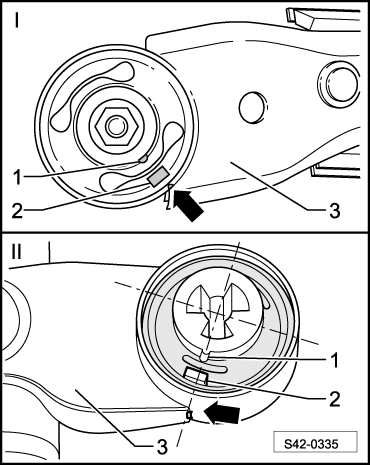
Fitting position of the rubber-metal bearing
–  Align orientation nubs -1- or orientation bead -2- to edge of track control arm -3--arrow-.
  S42-0335
–  Carefully depress the pedal of the hydraulic pump -VAS 6179--arrow A-.
The hydraulic cylinder -VAS 6178- is therefore activated.
  S42-0338
–  Insert the rubber-metal bearing -1- up to the stop into the axle body -2-.
–  Check the fitting position of the rubber-metal bearing.
  S42-0341
–  Carefully depress the pedal of the hydraulic pump -VAS 6179--arrow B-.
While doing so, the hydraulic cylinder -VAS 6178- returns to the initial position.
–  Remove assembly devices and unscrew assembly device (nut) -T10254/4-.
–  Grease the kidney-shaped cavities of the rubber-metal bearing with assembly paste -G052 150 A2-.
–  Carefully raise the rear axle so that the rubber-metal bearing engages in the bearing brackets for the axle.
  S42-0338
–  Insert the new fixing screws -1- from the outside of the vehicle into the bearing brackets for the axle.
–  Screw new nuts onto the fixing screws -1- for bearing brackets of the rear axle and tighten.
  Note
When tightening the rubber-metal bearing screws and nuts, the axle body must be in the unladen condition (unladen weight position) → Chapter.
Vehicles with ABS
–  Hook on the ABS line in the clips.
  S42-0147
Vehicles fitted with load-sensitive brake pressure regulator (vehicles without ABS)
–  Screw in the screw -1-.
–  Inspecting or adjusting the brake-power regulator → Chapter.
Only on vehicles equipped with an Xenon headlights
–  Connect the tension rod for the sender at the rear → Electrical System; Rep. gr.94.
Continued for all vehicles
–  Hook on the brake lines in the right line holder.
  S42-0148
–  Attach the brake line holder -2- to the vehicle body, left -arrow A-.
  Note
When installing the hand brake cables, pay attention to the correct fitting position → Chapter.
  N42-0501
–  Hook hand brake cables into the holders -arrows- (on both vehicle sides).
–  Screw in screws of front wheelhouse liners on both vehicle sides → Body Work; Rep. gr.66.
–  Attach the wheels.
  Note
It is necessary to perform a vehicle alignment in the event of → Chapter.
–  Perform a test drive.
–  Check the steering wheel position during the test drive.
  S42-0147
Tightening torque:
Rear axle to bearing bracket for axle
t  Use new screws and nuts!
t  Tighten in unladen weight position → Chapter
45 Nm + 90°
Brake line holder to vehicle body16 Nm
Screw for brake-power regulator16 Nm
Wheel bolts120 Nm


Rear axle with disc brake > < Replacing the rubber-metal bearing - version 1