skoda Workshop Repair Guides

Skoda Fabia Workshop & Repair Manuals | Auto Service

Installing the power-assisted steering gear TRW - RHD version > < installing the power-assisted steering gear - LHD version
Removing the power-assisted steering gear TRW - RHD version
  Caution
Bring the steering wheel in its central position (with the wheels straight ahead) and make sure that it does not turn during repairs as this could damage the coil spring of the airbag unit.
   
–  Secure the steering wheel with the wheels in straight ahead position with adhesive tape -arrow- against unintended turning.
  S48-0196
–  Unscrew plastic nuts -1-.
–  Remove cover -2-.
  S48-0106
–  Release screw -1-.
–  Remove universal joint in the direction of the arrow from the input shaft of the power-steering gear.
–  Before disconnecting the battery determine the code of radio sets fitted with anti-theft coding.
  Note
Because of the different dimensions of the battery the screw cap of the hydraulic oil reservoir on certain vehicle versions is concealed by the battery tray and battery. If this is the case remove the battery and the battery tray.
–  Disconnect battery → Electrical System; Rep. gr.27.
–  If necessary remove air filter → Engine, Fuel Injection; Rep. gr.24 (petrol engines) or → Engine, Fuel Injection; Rep. gr.23 (diesel engines).
–  If necessary remove the battery and battery tray → Electrical System; Rep. gr.27.
  S48-0107
–  Unhook cable of power-steering sensor -G250- from line holder -arrows-.
–  Raise vehicle.
–  Remove the sound dampening system → Body Work; Rep. gr.50.
–  Remove wheels at the front.
Vehicles with the exhaust system below the assembly carrier
–  Remove front exhaust pipe → Engine, Mechanics; Rep. gr.26.
Continued for all vehicles
  S48-0109
–  Unscrew the screws -1- and -2- of the pendulum support.
  S48-0112
–  Screw out the left and right nuts -1-.
–  Pull out left and right coupling rod -3- from stabilizer -2-.
  S48-0113
–  Screw up nut of the track rod end -1- sufficiently so that the ball joint extractor -3287A- is supported on the nut.
–  Use ball joint extractor -3287A- to press track rod/track rod end -2- off the steering arm.
–  Screw off the nut on both sides from the track rod end.
–  Pull track rod end on both sides out of steering arm.
  N48-0601
–  Unscrew the screwed lid -1- for the hydraulic oil reservoir -2- of the engine pump aggregate.
–  Extract the hydraulic oil with an extraction bottle via the filler neck.
  Note
t  After extraction there will be residual hydraulic oil in the engine pump aggregate as well as in the return line and pressure line (expansion hose).
t  Do not use drained hydraulic oil again.
t  Do not pinch off the expansion hose and the return hose with hose clamps -MP7-602 (3094)- or any other tools. Pinching off may result in damage to the expansion hose and return hose.
t  To avoid damage make sure the bending radius of at least 100 mm is respected when bending or tying up the expansion hose or return hose.
–  Place the catch pan to catch drained off hydraulic oil under the steering gear.
  S48-0147
–  Insert wooden insert (490 x 270 x 50 mm) -2- in the adapter, e.g. -V.A.G 1359/2-.
–  Position engine/gearbox jack with adapter and support assembly carrier.
–  Unscrew bolts -1- for power-steering gear.
  Note
t  Note the following work steps and absolutely ensure that you follow the sequence.
t  The fixing bolts for -T10096- must only be tightened to maximum 20 Nm as otherwise the fixing bolt thread becomes damaged.
  S48-0116
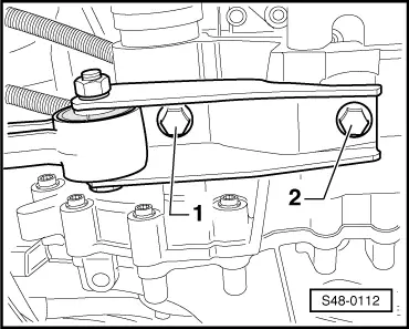
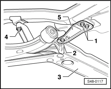
–  Unscrew left screw -4- for assembly carrier -3-, screw in a fixing bolt of -T10096- and tighten to 20 Nm.
–  Unscrew right screw -4- for assembly carrier (not shown in figure), screw in fixing bolt of - T10096- and tighten to 20 Nm.
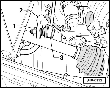
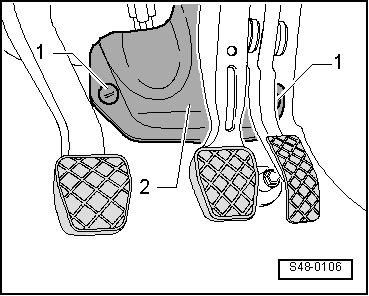
–  Unscrew bolts -1- on both sides.
–  Unscrew the left screw -2- and remove support -5-.
–  Screw in fixing bolts of -T10096- to 20 Nm.
–  Unscrew the right screw -2- and remove support -5-.
–  Screw in fixing bolts of -T10096- to 20 Nm.
The fixing of the assembly carrier is completed once all 4 screws (Pos. -2- and -4-) are consecutively replaced with the fixing bolts.
  S48-0117
–  Release pressure line from spacer holder -arrow-.
  Caution
When lowering the assembly carrier make sure that the pressure line, return hose and the line of the power-assisted steering sensor -G250- are not exposed to traction.
  S48-0125
–  Lower subframe -4- about 4 cm.
5 - Fixing bolt of - T10096-
–  Unscrew pressure line (expansion hose) -1- and return line (return hose) -2- on the power-steering gear.
–  Shut off the pressure line and return line with a plastic bag and adhesive tape.
–  Shut off the threaded bores (connections for pressure and return lines) on the power-steering gear with plastig screw plugs.
  S48-0351
–  Remove clip -1- and thus slacken pressure line and return line.
–  Tie up the pressure line and return line.
  S48-0353
–  Unscrew Allan screws -1-.
–  Remove the power-assisted steering sensor -G250- (-2-) with seal -3- out of the power-steering gear valve housing.
The new removal of the power-assisted steering sensor -G250- with adapter cable is illustrated in the figure. The removal of the power-assisted steering sensor -G250- with fixed connection line occurs in the same way.
  Note
When lowering the assembly carrier make sure there is sufficient clearance between the drive shafts and the stabilizer.
–  Slowly lower the assembly carrier with engine/gearbox jack and adapter.
–  Remove power-steering gear towards the rear.
  S48-0259

Installing the power-assisted steering gear TRW - RHD version > < installing the power-assisted steering gear - LHD version