| –
| Test the values for the electronic throttle potentiometer voltages. |

Note | The engine control unit converts the voltage values in percentage (in relation to 5 Volts). 5 Volts power supply correspond to 100%. |
| –
| Observe display fields 1 and 2. |
| –
| Slowly press the accelerator pedal fully down. |
| The percentage indication in display field 1 must rise gradually. The tolerance range 0…100 % is not fully used up. |
| The percentage indication in display field 2 must drop gradually. The tolerance range 100…0 % is not fully used up. |
Note | t
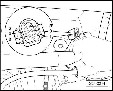
| The reason why the display in display field 1 rises and the display in display field 2 drops lies in the opposition of the potentiometer (angle sender) in the throttle valve control unit -J338-. |
| t
| This means that the voltage tapping of angle sender 1 runs towards the 5 Volts (the further the throttle valve is opened the greater the voltage; the percentage indication rises). |
| t
| The voltage tapping of angle sender 2 runs away from the 5 Volts towards 0 Volt (the further the throttle valve is opened the lower the voltage: the percentage indication drops). |
| If the display does not occur as described: |
| –
| Select function 06 “End output” and confirm with Q. |
|
|
Reading measured value block 62 -> | 15,0 % 75,0 % 15,0 % 7,0 % |
|