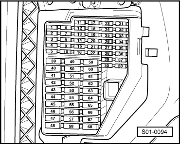
Fabia Mk1
|
|
|
|
|
|

|
|
|
|
|
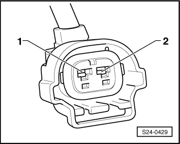
| Plug connection on cylinder | Contact | Bush | |
| 1 | 2 | 88 | |
| 2 | 2 | 87 | |
| 3 | 2 | 85 | |
| 4 | 2 | 86 |
|
|
|

|
|
|
|
|
|
|
|
|
|
|
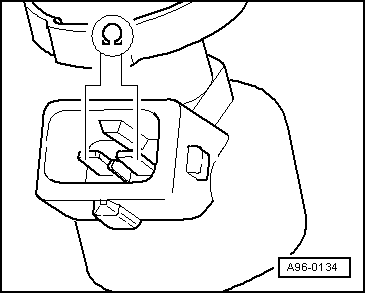
| Plug connection on cylinder | Contact | Bush | |
| 1 | 2 | 88 | |
| 2 | 2 | 87 | |
| 3 | 2 | 85 | |
| 4 | 2 | 86 |
|
|
|