
Fabia Mk1
|
| Reading measured value block 30 | → | < Readout on display | |||||
| xxx | xxx | ||||||
| 1 | 2 | 3 | 4 | < Display field | Specification | Analysis | |
| no display | --- | --- | |||||
| no display | --- | --- | |||||
| Status of lambda probe after catalytic converter and lamda control 1) | 11X | → Anchor | |||||
| Status of lambda probe before the catalytic converter and lambda control | 111 | → Anchor | |||||
| 1) only engines with identification characters AQV, ATZ, AQW, AZF |
|
| Meaning, if display positions = 1 | ||||
| X | X | X | Operating position | |
| 1 | Lambda probe heater active | |||
| 1 | Lambda probe operational | |||
| 1 | Lambda controller active | |||
|
| Reading measured value block 31 | → | < Readout on display | |||||
| x.xx V | x.xx V | ||||||
| 1 | 2 | 3 | 4 | < Display field | Specification | Analysis | |
| no display | --- | --- | |||||
| no display | --- | --- | |||||
| Disregard display | --- | --- | |||||
| Lambda probe voltage before catalyst | 0.00…1.00 V | → Anchor | |||||
 Note
Note
|
| Display field 1 | Possible cause of fault | Rectifying fault | |||||||||||||||||||||||||||
| constant 0.00...0.30 V or constant 0.70...1.00 V |
|
| |||||||||||||||||||||||||||
| constant 1.00 V | Short-circuit to positive terminal in:
|
| |||||||||||||||||||||||||||
| between 0.40...0.50 V | Line interruption in:
| ||||||||||||||||||||||||||||
| constant 0.00 V | Short-circuit to earth in:
|
|
| Reading measured value block 31 | → | < Readout on display | |||||
| x.xxxx | x.xxxx | ||||||
| 1 | 2 | 3 | 4 | < Display field | Specification | Analysis | |
| no display | --- | --- | |||||
| no display | --- | --- | |||||
| Lambda nominal value Bank 1 | 0,9900…1,0100 | --- | |||||
| Lambda actual value Bank 1 | 0,9600…1,0400 | --- | |||||
|
| Read measured value block 32 → | ⇐ Read out on display: | ||||||
| xx.x % | xx.x % | — | — | ||||
| 1 | 2 | 3 | 4 | ⇐ Display field | Specification | Analysis: | |
| — | — | ||||||
| — | — | ||||||
| Lambda learned value under partial load (multiplicative) upstream of catalytic converter | -10,0...10,0 % | → Anchor | |||||
| Lambda learned value in idling (additive) upstream of catalytic converter | -10,0...10,0 % | → Anchor | |||||
Note
|
| Display field | Readout on display: | Possible cause of fault | Rectifying fault | |||||
| 1 and 2 | low lambda learned values |
|
| |||||
|
| |||||||
|
| |||||||
|
| |||||||
|
| |||||||
| Display field | Readout on display: | Possible cause of fault | Rectifying fault | |||||
| 1 and 2 | high lambda initialisation values |
|
| |||||
|
| |||||||
|
| |||||||
|
| |||||||
|
| |||||||
|
| |||||||
|
| Reading measured value block 33 | → | < Readout on display | |||||
| xx.x % | x.xxx V | ||||||
| 1 | 2 | 3 | 4 | < Display field | Specification | Analysis | |
| no display | --- | --- | |||||
| no display | --- | --- | |||||
| Lambda probe voltage before catalyst | 1,40 ... 1,60 V | → Anchor | |||||
| Lambda regulator upstream of catalytic converter | -10,0…10,0 % | → Anchor | |||||
Note
|
| System in basic setting 34 | → | < Readout on display | |||||
| xxxx rpm | xxxx °C | x.xxx | Text | ||||
| 1 | 2 | 3 | 4 | < Display field | Specification | Analysis | |
| Result of ageing test of the lambda probe before catalyst (Test OFF / Test ON / B1 S1 O.K. / B1 S1 N.O.K.) | B1-S1 o.k. | --- | |||||
| Disregard display | - | --- | |||||
| Catalytic converter temperature | min. 400 °C | --- | |||||
| Engine speed 1.0 ltr. engine 1.4 ltr. engine | 1100 …1700 rpm | --- | |||||
|
| System in basic setting 36 → | ⇐ Read out on display: | ||||||
| x.xxx V | Text | — | — | ||||
| 1 | 2 | 3 | 4 | ⇐ Display field | Specification | Analysis: | |
| — | — | ||||||
| — | — | ||||||
| Test lambda probe downstream of catalytic converter (Test OFF/Test ON/ B1 S2 o.k. / B1 S2 n.o.k.) | B1 S2 o.k. | — | |||||
| Lambda probe voltage after catalytic converter | 0.000...1.000 V | → Anchor | |||||
|
| Display field | Readout on display: | Possible cause of fault | Rectifying fault | |||||||
| 1 | constant 1,100 V |
|
| |||||||
| constant between 0.400 ...0.500 V |
| |||||||||
| constant 0.000 V |
| |||||||||
|
| System in basic setting 37 → | ⇐ Read out on display: | ||||||
| xx.x % | x.xxx V | x.x % | Text | ||||
| 1 | 2 | 3 | 4 | ⇐ Display field | Specification | Analysis: | |
| Test lambda probes (Test ON / Test OFF / Syst. O.K. / Syst. N.O.K.) | B1-S1 o.k. | — | |||||
| Ignore | — | — | |||||
| Lambda probe voltage after catalytic converter | 0.000...1.000 V | → Anchor | |||||
| Engine load | 12,0...40,0 % | — | |||||
Note
|
| Read measured value block 41 → | ⇐ Read out on display: | ||||||
| — | Text | xxx ohms | Text | ||||
| 1 | 2 | 3 | 4 | ⇐ Display field | Specification | Analysis: | |
| Lambda probe heating downstream of catalytic converter | Ht. after c. ON Ht. after c. OFF | — | |||||
| Resistance lambda probe heating downstream of catalytic converter | — | — | |||||
| Lambda probe heating upstream of catalytic converter | Ht. bf. c. ON Ht. bf. c. OFF | — | |||||
| — | — | ||||||
Note
|
| System in basic setting 43 | → | < Readout on display | |||||
| xxxx rpm | xxxx °C | x.xx V | Text | ||||
| 1 | 2 | 3 | 4 | < Display field | Specification | Analysis | |
| Result of ageing test of the lambda probe after catalyst (Test OFF / Test ON / B1-S2 O.K. / B1-S2 N.O.K.) | B1-S2 o.k. | --- | |||||
| Lambda probe voltage after catalytic converter | 0.00 bis 1.00 V | → Anchor | |||||
| Catalytic converter temperature | min. 400 °C | --- | |||||
| Engine speed 1.0 ltr. engine 1.4 ltr. engine | 1100 …1700 rpm | --- | |||||
|
| System in basic setting 46 | → | < Readout on display | |||||
| xxxx rpm | xxxx °C | x.xx | Text | ||||
| 1 | 2 | 3 | 4 | < Display field | Specification | Analysis | |
| Result of catalyst inspection (TEST OFF/TEST ON/Cat. B1 O.K./Cat. B1 N.O.K.) | Cat B1 o.k. | --- | |||||
| Catalyst efficiency | 0,50...1,00 | --- | |||||
| Catalytic converter temperature | min. 400 °C | --- | |||||
| Engine speed 1.0 ltr. engine 1.4 ltr. engine | 1100 …1700 rpm | --- | |||||
|
| Read measured value block 99 → | ⇐ Read out on display: | ||||||
| xxxx rpm | xxx °C | xx.x % | Text | ||||
| 1 | 2 | 3 | 4 | ⇐ Display field | Specification | Analysis: | |
| Operating condition of lambda control | OFF ON | — | |||||
| Lambda control before catalyst | -10,0…10,0 % | → Anchor | |||||
| Coolant temperature | 80...115 °C | — | |||||
| Engine speed (idling speed) 1.0 ltr. engine 1.4 ltr. engine | 630...770 rpm 730...870 rpm | — | |||||
|
| Reading measured value block 50 | → | < Readout on display | |||||
| xxx rpm | xxx rpm | Text | Text | ||||
| 1 | 2 | 3 | 4 | < Display field | Specification | Analysis | |
| Air conditioning compressor on, off | Compr. OFF | --- | |||||
| Disregard display | --- | --- | |||||
| Engine speed (idling speed nominal value) 1.0 ltr. engine 1.4 ltr. engine | 700 rpm 800 rpm | --- | |||||
| Engine speed (idling speed) 1.0 ltr. engine 1.4 ltr. engine | 630...770 rpm 730...870 rpm | --- | |||||
|
| Reading measured value block 54 | → | < Readout on display | |||||
| xxx rpm | Text | xx.x % | x.x % | ||||
| 1 | 2 | 3 | 4 | < Display field | Specification | Analysis | |
| Disregard display | --- | --- | |||||
| Sender 1 for accelerator pedal position | 10,0...20,0 % | --- | |||||
| Operating condition (idling, enrichment, partial load, full load, overrun fuel cut-off) | Idling | --- | |||||
| Engine speed (idling speed) 1.0 ltr. engine 1.4 ltr. engine | 630...770 rpm 730...870 rpm | --- | |||||
|
| Read measured value block 55 → | ⇐ Read out on display: | ||||||
| xxxx rpm | xx Nm | xx.x % | xxxxx | ||||
| 1 | 2 | 3 | 4 | ⇐ Display field | Specification | Analysis: | |
| Operating conditions | xxxxx | → Anchor | |||||
| Initialisation value idling control | |||||||
| Air conditioning on | -6,0...8,0 % | — | |||||
| Air conditioning off | -3,0...8,0 % | ||||||
| Idling control | 5,0...40,0 % | — | |||||
| Engine speed (idling speed) 1.0 ltr. engine 1.4 ltr. engine | 630...770 rpm 730...870 rpm | --- | |||||
Note
|
| Meaning if display positions = 1 | |||||
| 1 | 2 | 3 | 4 | 5 | Meaning |
| 1 | Air conditioning compressor on | ||||
| x | No meaning | ||||
| 1 | Air conditioning switched on | ||||
| x | No meaning | ||||
| x | No meaning | ||||
|
| Read measured value block 62 → | < Readout on display | |||||||
| xx.x % | xx.x % | xx.x % | xx.x % | |||||
| 1 | 2 | 3 | 4 | < Display field | Specification | Analysis | ||
| Do not actuate pedal | Actuate pedal | |||||||
| Accelerator pedal position sender 2 -G185- | 3…10 % | 35,0…50,0 % | --- | |||||
| Accelerator pedal position sender 1 -G79- | 6…20 % | 67,0…97,0 % | --- | |||||
| Throttle valve angle ( throttle valve drive angle sender 2 for electric power control - G188- ) | 82,0…97,0 % | 3,0…16,0 % | --- | |||||
| Throttle valve angle ( throttle valve drive angle sender 1 for electric power control -G187- ) | 3,0…16,0 % | 82,0…93,0 % | --- | |||||
| Notes on display group 062: |
| t | The potentiometers (throttle valve drive angle sender 2 for electric power control) of the throttle valve control unit and of the accelerator pedal position sender are duplicated for safety reasons. The engine control unit permanently inspects the correctness of the potentiometer. |
| t | The value of accelerator pedal position sender 2 -G185- must always be half of the value of accelerator pedal position sender 2 - G79-. |
| t | The potentiometers of the throttle valve control unit contra-rotate. The value of both potentiometers together must always be approx. 100%. |
| t | The specifications stated above are not fully utilised. |
|
| Reading measured value block 66 | → | < Readout on display | |||||
| xxx km/h | xxxx | xxx km/h | xxxx | ||||
| 1 | 2 | 3 | 4 | < Display field | Specification | Analysis | |
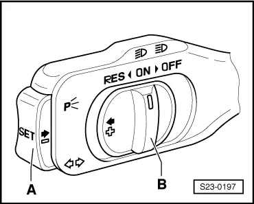
| Switch position on the actuating lever of the CCS 1) | 0000 0000 | ||||||
| Driving speed (nominal); last value stored by the CCS | x km/h | --- | |||||
| Switch position of brake, clutch and CCS | 0000 or 00000000 | ||||||
| Driving speed (actual) | xxx km/h | --- | |||||
| 1) The 8-digit number block must not be shown on all vehicles. |
|
| 0000 | X | X | X | X | Meaning, if display positions = 1 | |
| 1 | Cruise control system deactivated | |||||
| 1 | Clutch depressed | |||||
| 1 | Brake pressed (brake pedal switch) | |||||
| 1 | Brake pressed (brake light switch) |
|
|
| 0000 | X | X | X | X | Meaning | |
| 0 | 0 | 0 | 0 | Switch -B- locked to “OFF” | ||
| 0 | 0 | 0 | 1 | Switch -B- to “OFF” before operating point | ||
| 0 | 0 | 1 | 1 | Switch -B- to “ON” | ||
| 1 | 0 | 1 | 1 | Switch -B- to “RES” | ||
| 0 | 1 | 1 | 1 | Switch -A- pressed (switch -B- to “ON”) |
|
| System in basic setting 70 → | ⇐ Read out on display: | ||||||
| x.x % | x.x % | x.x % | Text | ||||
| 1 | 2 | 3 | 4 | ⇐ Display field | Specification | Analysis: | |
| Result of the activated charcoal filter system diagnosis (Test OFF/ Test ON/ TVV O.K./ TVV N.O.K.) | TVV o.k. | — | |||||
| Idling speed controller variation during TVV diagnosis | -5,0…5,0 % | — | |||||
| Lambda controller variation during TVV diagnosis | -15,0…15,0 % | — | |||||
| TVV control -N80- | 0,0…100 % | — | |||||
Note
|
| Read measured value block 100 → | ⇐ Read out on display: | ||||||
| xxxxxxxx | xxx.x °C | xxx s | xxxxxxxx | ||||
| 1 | 2 | 3 | 4 | ⇐ Display field | Specification | Analysis: | |
| Diagnosis status | — | — | |||||
| Time since engine start | — | — | |||||
| Coolant temperature | 80.0...110.0 °C | → Chapter 01-5 | |||||
| Readiness code | 00000000 | ||||||
|
| The readiness code is only generated if all the display positions show 0 | ||||||||
| 1 | 2 | 3 | 4 | 5 | 6 | 7 | 8 | Diagnosis function |
| 0 | Catalytic converter | |||||||
| 0 | Catalytic converter heating (no diagnosis at present/always “0”) | |||||||
| 0 | Activated charcoal filter system (tank ventilation system) | |||||||
| 0 | Secondary air injection system (not fitted/always “0”) | |||||||
| 0 | Air conditioning system (currently no diagnosis/always “0”) | |||||||
| 0 | Lambda probes | |||||||
| 0 | Lambda probe heater | |||||||
| 0 | Exhaust gas recirculation | |||||||
|
| Read measured value block 120 → | ⇐ Read out on display: | ||||||
| xxxx rpm | xxx Nm | xxx Nm | Text | ||||
| 1 | 2 | 3 | 4 | ⇐ Display field | Specification | Analysis: | |
| Status | TCS active / TCS inactive | — | |||||
| Actual engine load | — | — | |||||
| Nominal engine load | — | — | |||||
| Engine speed | xxxx rpm | — | |||||
|
| Read measured value block 125 → | ⇐ Read out on display: | ||||||
| Text | Text | Text | Text | ||||
| 1 | 2 | 3 | 4 | ⇐ Display field | Specification | Analysis: | |
| Status airbag | Airbag 1 | ||||||
| Status of combiinstrument | Combi 1 | ||||||
| --- | --- | — | |||||
| Status ABS | ABS 1 | ||||||
|
| Read measured value block 126 → | ⇐ Read out on display: | ||||||
| Text | Text | Text | Text | ||||
| 1 | 2 | 3 | 4 | ⇐ Display field | Specification | Analysis: | |
| --- | --- | — | |||||
| --- | --- | — | |||||
| Status of the vehicle voltage control unit | El. CU 1 | ||||||
| Status of the air-conditioning system | Clima 1 | ||||||
Note
|
| Display -V.A.G 1552- | Possible cause of fault | Rectifying fault | |||||||
| if 0 displayed instead of 1 |
|
| |||||||
|