Note | t
| The engine is removed towards the front together with the gearbox. |
| t
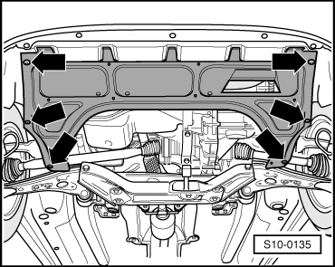
| Supporting points for lift platform → Fabia. |
| t
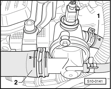
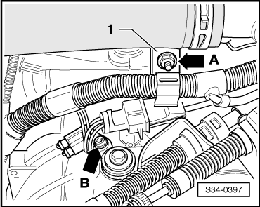
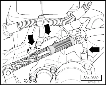
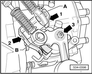
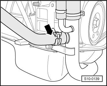
| The hose connections are secured with screw-type clips, spring-type clips or clamp-type clips. Replace warm-type clamps with spring strap clips or screw clamps. |
| t
| Fuel hoses at the engine must only be secured with spring-type clips. The use of clamp-type or screw-type clips is not allowed. |
| t
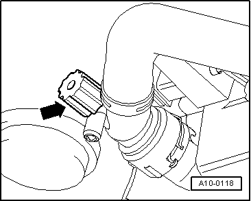
| Use pliers for spring strap clips to fit the spring strap clips. |
| t
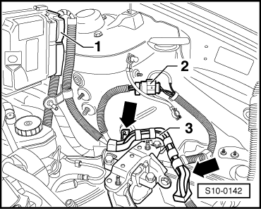
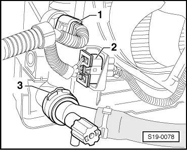
| Pay attention to the correct assignment of the plugs, if necessary mark. |
| –
| On models fitted with a coded radio set, pay attention to the coding; determine if necessary. |
|
|
|

 WARNING
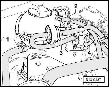
 Caution