skoda Workshop Repair Guides

Skoda Workshop Service and Repair Manuals

Removing and installing ignition coils with power output stages > < Testing secondary resistances
Check ignition coils with power output stage (engines with engine identification characters BBY, BKY, BBZ, BUD)
Special tools and workshop equipment required
t  
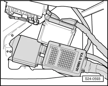
Test box -V.A.G 1598/31- or -V.A.G 1598/22-
t  Handheld multimeter, e.g. -V.A.G 1526 B-
t  Measuring tool set, e.g. -V.A.G 1594 C-
t  Diode test lamp, e.g. -V.A.G 1527-
t  Current flow diagram
Test sequence
  Note
Ignition coil and power output stage form a building unit.
Cylinder, which does not operate or misfire, determine as follows:
–  Test combustion misfiring → Chapter.
If a combustion misfiring was detected:
–  Proceed with test on cylinder determined as defective.
If no combustion misfiring was detected:
–  Successively remove contacts of the injectors while engine is running and monitor engine run,
or
–  Compare spark plugs of all cylinders and pay attention to contaminated (covered with soot) electrodes.
If a defective cylinder was determined:
–  Replace the spark plug of the defective cylinder with the one of another cylinder.
If the fault on this spark plug still exists:
–  Replace spark plug.
If the given cylinder is still defective:
–  Replace the ignition coil of the defective cylinder with the one of another cylinder.
If the fault on this ignition coil still exists:
–  Replace ignition coil.
If the given cylinder is still defective:
–  Disconnect the 4-pin plugs -1...4- at the ignition coils and check the wiring → Current flow diagrams and Fitting locations.
Checking voltage supply
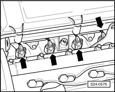
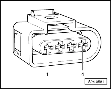
–  Unplug the 4 pin plug connections from all ignition coils.
Test conditions
l  The fuses of the ignition system must be in proper order → Current flow diagrams and Fitting locations.
   
–  Measure the voltage supply beween contacts 1 + 3 and 2 + 3 of the removed plug using the multimeter and the adapter cables from the measuring tool set.
–  Switch on ignition.
Specified value: min. 11.5 V
–  Switch off ignition.
If no voltage is present:
  S24-0581
–  Check the cable between 4-pin plug contact 3 and the relay plate for interruption according to the Current Flow Diagram.
Cable resistance: max. 1.5 Ω
–  Check the cable between 4-pin plug contact 2 + earth and contact 1 + earth for interruption according to the Current Flow Diagram.
Cable resistance: max. 1.5 Ω
Test control
  WARNING
Caution! During the following test do not touch neither the connecting parts of the ignition coils nor the auxiliary cables.
  S24-0581
–  Unplug connector -arrows- of the injectors.
  S24-0576
–  Connect the diode test lamp V.A.G 1527 with adapter cables from V.A.G 1594 to contacts 3 + 4 of the removed plug.
–  Actuate the starter and check the ignition signal on the engine control unit.
The LED must light up.
–  Switch off ignition.
If the diode lights up and there is a voltage existing between contacts 3 + 4:
–  Replace ignition coil → Chapter.
If the LED does not light up:
–  Check wires.
Check wires.
  S24-0581
–  Connect the test box -V.A.G 1598/31- or -V.A.G 1598/22- to the wiring loom of the control unit. The engine control unit is not connected here.
  S24-0593
–  Check wiring between the test box and the 4-pin plug for interruption according to the current flow diagram → Current flow diagrams and Fitting locations.
Cable resistance: max. 1.5 Ω
–  Also check the wires for short-circuits.
Specified value: ∞ Ω
If no fault has been determined on the wiring and there is a voltage between contacts 2 + 3:
–  Replace engine control unit → Chapter.
  S24-0581

Removing and installing ignition coils with power output stages > < Testing secondary resistances