skoda Workshop Repair Guides

Skoda Workshop Service and Repair Manuals

Check sender for coolant temperature G62 > < Testing Intake manifold pressure sender G71
Testing Intake manifold temperature senderG42/G72
Testing Intake manifold temperature sender -G42/G72-
  Note
Only use gilded contacts to repair contacts in the plug connection of the sender.
Special tools and workshop equipment required
t  Vehicle system tester e.g. -V.A.G 1552- with cable -V.A.G 1551/3, 3A, 3B, 3C-
t  Test box -V.A.G 1598/31- or -V.A.G 1598/22-
t  Handheld multimeter, e.g. -V.A.G 1526 B-
t  Measuring tool set, e.g. -V.A.G 1594 C-
t  Current flow diagram
Test sequence
–  Connect vehicle system tester -V.A.G 1552-. Switch ignition on and select address word 01 “Engine electronics” → Chapter.
–  Select function 08 “Read measured value block” and display group 004.
   
–  Read off intake manifold temperature value in display field 4.
Specified value: ambient temperature → Note
If implausible value appears in the display:
–  Select function 06 “End output” and switch ignition off.
1)  If a temperature is displayed that is below the ambient temperature of the sender, check the sender wires for transition impedances. Make sure that the sender heats up or is heated by radiant heat.
 
Reading measured value block 4     ->
 770 rpm     14.1V       89°C       32°C
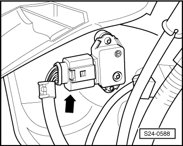
–  Disconnect the 4-pin plug connection from the intake manifold temperature sender -G42/G72- with intake manifold pressure sender -G71--arrow-.
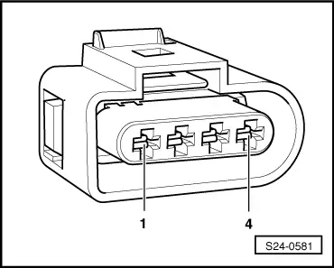
–  Connect the multimeter for resistance measurement to contacts 1 and 2 of the intake manifold temperature sender.
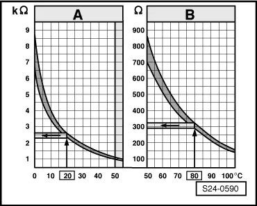
Specified value:
  S24-0588
The specified value in field A applies for the temperature range 0...50°C, the specified value in field B applies for the temperature range 50...105°C.
Example:
t  For a temperature of 20°C the specification is 2.3...2.6 kΩ
t  The specified value for the temperature of 80°C is 290...330 Ω
If the specified value is not reached:
–  Replace intake manifold pressure sender -G71- with intake manifold temperature sender -G42/G72- → Chapter.
If the specified value is reached:
–  Connect test box - V.A.G 1598/31- or -V.A.G 1598/22 - to the wiring loom of the control unit → Chapter. The engine control unit is not connected here.
  S24-0590
–  Check wiring between the test box and the 4-pin plug for interruption according to the current flow diagram → Current flow diagrams and Fitting locations
Cable resistance: max. 1.5 Ω
–  Additionally check the cable for a short circuit to battery positive.
Specified value: ∞ Ω
If the lines are not found to be faulty:
–  Replace engine control unit → Chapter.
  S24-0581

Check sender for coolant temperature G62 > < Testing Intake manifold pressure sender G71