skoda Workshop Repair Guides

Skoda Workshop Service and Repair Manuals

Testing resistances of the injection valves > < Testing injection valves
Test control
Test control
Special tools and workshop equipment required
t  Test box -V.A.G 1598/31- or -V.A.G 1598/22-
t  Handheld multimeter, e.g. -V.A.G 1526 B-
t  Diode test lamp, e.g. -V.A.G 1527-
t  Measuring tool set, e.g. -V.A.G 1594 C-
t  Current flow diagram
t  Extractor -T 10094 A-
Test conditions
   
l  Fuse 35 must be OK
l  Earth connections between the engine (on gearbox housing) and body (under battery) are o.k.
l  Battery voltage at least 11.5 V.
l  Engine speed sender o.k.; check → Chapter.
l  
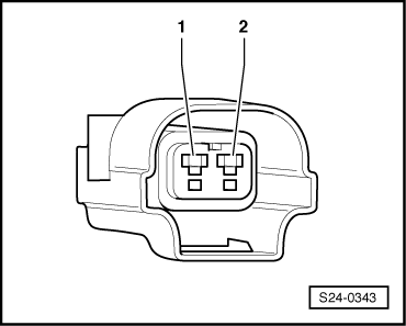
The hall sender must be OK, test it → Chapter.
l  Fuel pump relay OK
Test sequence
Engines with engine identification characters AUA, AUB, BBY, BBZ, BKY
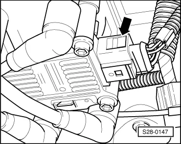
–  Remove engine cover with air filter → Chapter.
Engines with engine identification characters AUA, AUB
  S01-0094
–  Unplug the 4-pin connector -arrow- from the ignition transformer.
Engines with engine identification characters BBY, BBZ, BKY
–  Slightly pull out all the ignition coils with the extractor -T 10094 A- and disconnect the plug connections → Chapter.
Engines with engine identification characters BUD
–  Engine cover → 1.4/55; 1.4/59; 1.4/74 Engine - Mechanics → Rep. Gr.15
–  Slightly pull out all the ignition coils with the extractor -T 10094 A- and disconnect the plug connections → Chapter.
Continued for all engines
  S28-0147
–  Unplug connector -arrows- of the injectors.
  S24-0576
–  Connect up the diode test lamp to the contacts of the plug for cylinder 1.
–  Actuate the starter and check the power supply to the injection valve of cylinder 1.
LED must flash.
–  Repeat the test on the injection valves of cylinders 2 to 4 in sequence.
–  Switch off ignition.
If the LED does not light up on any cylinder:
  S24-0344
–  Connect the diode test lamp to the plug connection on cylinder 1, contact 1 and earth.
–  Actuate the starter and check the power supply to the injection valve of cylinder 1.
LED must flash.
–  Repeat test on the plug connections for the injection valves on cylinder 2 to 4.
If the LED does not flash:
–  Switch off ignition.
–  Check the cable between the 2-pin plug contact 1 and the fuel pump relay -J17- for interruption according to the current flow diagram → Current flow diagrams and Fitting locations.
Cable resistance: max. 1.5 Ω
If the LED does not light up on one or more cylinders:
–  Connect test box - V.A.G 1598/31- or -V.A.G 1598/22 - to the wiring loom of the control unit → Chapter. The engine control unit is not connected here.
  S24-0345
–  Check wiring between the test box and the 2-pin plugs of the injection valves for interruption according to the current flow diagram → Current flow diagrams and Fitting locations.
Cable resistance: max. 1.5 Ω
–  Test the cables for short circuiting with each other.
Specified value: ∞ Ω
–  Check wiring between contacts 1 of the plug connection on the injection valves for interruption of each other.
Cable resistance: max. 1.5 Ω
  S24-0343

Testing resistances of the injection valves > < Testing injection valves