
Fabia Mk1
| Connection diagram for vacuum hoses |
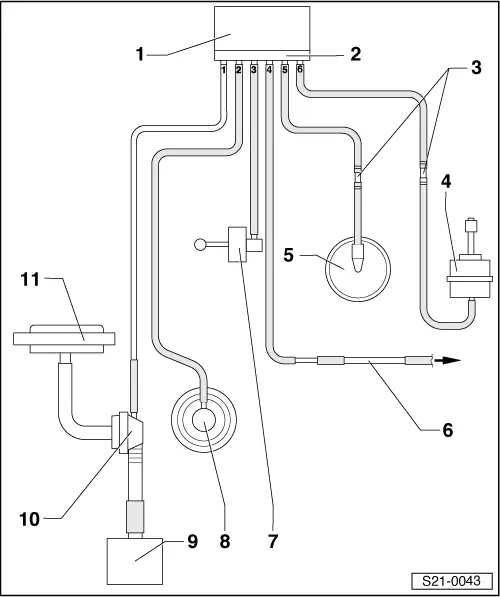
| 1 - | Valve block |
| q | Component parts of the valve block are: |
| t | Changeover valve for intake manifold flap -N239-: is installed in the engines with engine identification characters ASZ |
| t | Exhaust gas return valve -N18- |
| t | Solenoid valve for charge pressure control -N75- |
| 2 - | Connecting strip |
| q | Pay attention to the coding when connecting the vacuum hoses |
| 3 - | Connecting part |
| 4 - | Vacuum setting element |
| q | for charge pressure control |
| q | Component part of the exhaust turbocharger, not replaced separately |
| 5 - | Vacuum reservoir |
| 6 - | To air filter |
| 7 - | Vacuum unit |
| q | for intake manifold flap |
| q | is installed in the engines with engine identification characters ASZ |
| 8 - | Mechanical exhaust gas recirculation valve |
| 9 - | Tandem pump |
| 10 - | Distributor part |
| q | With non-return valve for brake servo unit |
| 11 - | Brake servo unit |