
Fabia Mk1
| Disassembling and assembling fuel distributor with injectors |
 Note
Note| Components marked with an * are checked by the self-diagnosis unit → Chapter. |
| For engine with engine identification characters AWY |
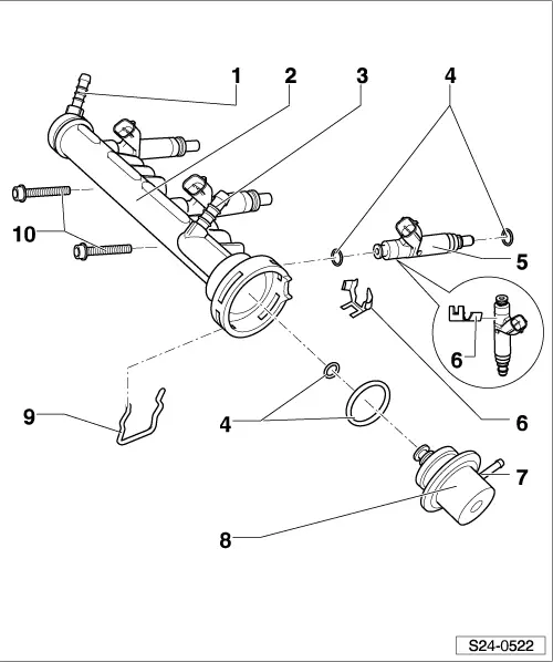
| 1 - | Connection for fuel supply hose |
| q | from fuel filter → 1.2/40; 1.2/47 Engine - Mechanics → Rep. Gr.20. |
| 2 - | Fuel distributor |
| 3 - | Connection for fuel return hose |
| q | for electrical fuel pump → 1.2/40; 1.2/47 Engine - Mechanics → Rep. Gr.20 |
| 4 - | O-ring |
| q | replace |
| 5 - | Injection valve -N30…N32 -* |
| q | mount with a retaining clip |
| q | before fitting O-rings moisten lightly with clean engine oil |
| q | Inspecting the injection rate, tightness and jet formation of the injectors → Chapter |
| q | resistance: 12…17 Ω (at approx. 20 °C) |
| 6 - | Retaining clip |
| q | check tightness on the injection valve and fuel distributor |
| 7 - | Connection for the pressure hose to the air filter |
| 8 - | Fuel pressure regulator |
| q | before fitting O-rings moisten lightly with clean engine oil |
| q | check → 1.2/40; 1.2/47 Engine - Mechanics → Rep. Gr.20 |
| 9 - | Retaining clip |
| q | check for correct seating on the fuel pressure regulator and fuel distributor |
| 10 - | 8 Nm |
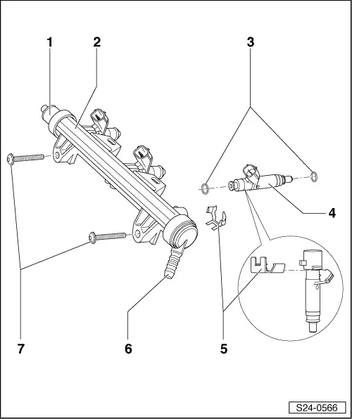
| For engine with engine identification characters BMD |

| 1 - | Connection for fuel supply hose |
| q | from fuel filter → 1.2/40; 1.2/47 Engine - Mechanics → Rep. Gr.20. |
| 2 - | Fuel distributor |
| 3 - | O-ring |
| q | replace |
| 4 - | Injection valve -N30…N32 -* |
| q | mount with a retaining clip |
| q | before fitting O-rings moisten lightly with clean engine oil |
| q | Inspecting the injection rate, tightness and jet formation of the injectors → Chapter |
| q | resistance: 12…17 Ω (at approx. 20 °C) |
| 5 - | Retaining clip |
| q | check tightness on the injection valve and fuel distributor |
| 6 - | Vent valve |
| q | Vent the fuel system → 1.2/40; 1.2/47 Engine - Mechanics → Rep. Gr.20 |
| 7 - | Cap for vent valve |
| 8 - | Retaining clip |
| q | pay attention to the correct position on the supports of the vent valve and the fuel distributor |
| 9 - | 8 Nm |
| For engine with engine identification characters AZQ, BME |
| 1 - | Bleeder supports |
| q | Vent the fuel system → 1.2/40; 1.2/47 Engine - Mechanics → Rep. Gr.20 |
| 2 - | Fuel distributor |
| 3 - | O-ring |
| q | replace |
| 4 - | Injection valve -N30…N32 -* |
| q | mount with a retaining clip |
| q | before fitting O-rings moisten lightly with clean engine oil |
| q | Inspecting the injection rate, tightness and jet formation of the injectors → Chapter |
| q | resistance: 12…17 Ω (at approx. 20 °C) |
| 5 - | Retaining clip |
| q | check tightness on the injection valve and fuel distributor |
| 6 - | Feed line |
| q | black with a white marking |
| q | secure with spring strap clamps |
| q | check for firm seating |
| q | from fuel filter |
| 7 - | 8 Nm |