skoda Workshop Repair Guides

Skoda Workshop Service and Repair Manuals

Testing clutch pedal switch F36 > < Testing the speed signal
Test brake light switchF and brake pedal switchF47
Test brake light switch -F- and brake pedal switch -F47-
As the injection system operates with an accelerator pedal position sender (potentiometer), which may become defective, for reasons of safety the engine is cut-off when the brake is activated. To do so the brake light switch signal and additionally the brake pedal swicth signal in the engine control unit is required.
If the brake pedal is activated with the accelerator pedal constantly pressed, the engine immediately slows down to idling speed. A defective brake pedal switch may result in involuntary cut-off procedures.
Special tools and workshop equipment required
t  Vehicle system tester -V.A.G 1552-
t  Diagnostic cable -V.A.G 1551/3, 3A, 3B oder 3C-
t  Hand multimeter (e.g. -V.A.G 1526 A-)
t  Adapter cable set (e.g. -V.A.G 1594 C-)
t  Test box -V.A.G 1598/31-
Test condition
l  Fuses No. 2 and No. 28 O.K.
Check for proper operation
–  Connect vehicle system tester -V.A.G 1552-. Switch ignition on and then select “address word” 01 Engine electronics → Chapter.
–  Select function 08 “Read measured value block” and display group 006.
   
Readout on display:
–  Note the contents of indicator 2.
   Specified value:
   X00 (if brake pedal not pressed)
   X11 (if brake pedal depressed)
–  Select function 06 “End output” and confirm with Q.
–  Switch off ignition.
–  If the display does not occur as described:
Testing switch
–  Remove lower part of the dash panel insert on the driver's side → Body Work; Rep. Gr.70.
–  Remove left footwell vent.
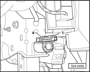
–  Unplug the plug connection at the brake light/brake pedal switch.
 
Reading measured value block         6   ->
0 km/h       000         0 %          0
–  Connect hand multimeter and measure the resistance between contacts 1 and 4.
   Specified value: ∞ Ω (no continuity)
–  Press down the brake pedal.
   Specified value: max. 1.5  Ω
  S24-0458
–  Connect hand multimeter and measure the resistance between contacts 2 and 3.
   Specified value: max. 1.5 Ω
–  Press down the brake pedal.
   Specified value: ∞ Ω (no continuity)
If the specified values are not reached:
–  Replace brake light/brake pedal switch.
If the specified values are reached:
Check supply voltage
  S24-0458
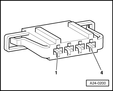
–  Connect up the hand multimeter and measure the voltage as follows:
  A24-0200
Plug connection contactSpecification
1 + earthapprox. battery voltage

–  Switch on ignition.
   
Plug connection contactSpecification
2 + earthapprox. battery voltage

If the specified values are not reached:
–  Check the cable between contact 1 of the plug and fuse 2 according to the current flow diagram for interruption → Current flow diagrams and Fitting locations.
–  Check the cable between contact 2 of the plug and fuse 28 according to the current flow diagram for interruption → Current flow diagrams and Fitting locations.
If the specified values are reached:
Checking wires
–  Switch off ignition.
–  Connect test box -V.A.G 1598/31- to wiring loom to engine control unit → Chapter.
   
–  Test the following cable connections for open circuit and for short circuit to earth and to positive:
  A24-0200
Plug connection contactTest box -V.A.G 1598/31-, bush 
365 
432

–  If necessary eliminate wire interruption or short-circuit.
   

Testing clutch pedal switch F36 > < Testing the speed signal