skoda Workshop Repair Guides

Skoda Workshop Service and Repair Manuals

Testing components > < Removing
Installing
Installing
–  Insert the injection pump in the holder and first secure the screw on the rear bracket.
   
–  Insert the front fixing screws -1- and tighten the screws to 30 Nm.
  S23-0109
–  Manually screw the injection pump gear with fixing screws -1- to the hub.
  Note
Pay attention to the different versions of fixing screws on the injection pump gear → Fig..
  S23-0098
–  Lock the injection pump gear with the rig pin -MP 1-301-.
–  Align the injection pump gear in middle position in the elongated holes.
–  Loosen the fixing bolt on the camshaft timing gear by 1 turn.
–  To this end use counterholder -MP 1-216- or -T30004-.
  S13-0229
–  Position the two-arm extractor -T40001- with the single-arm claw -A- and the two-arm claw -B- in the centre of the camshaft timing gear and extract camshaft timing gear.
   Counterhold the two-arm extractor with an open-end wrench -C-.
–  Check whether the TDC marking on the flywheel and the reference mark on the gearbox correspond.
–  Place the toothed belt on the injection pump gear and tensioning pulley.
–  Position the camshaft timing gear together with the toothed belt and attach with fixing bolts (the camshaft timing gear must still be able to rotate).
  M13-0002
–  Tighten the timing belt. To this end turn the nut wrench on the eccentric clockwise until the notch and the lobe -arrows- are opposite one another.
  Note
If the eccentric has been turned too far, the tensioning pulley must be fully slackened and tightened again. The eccentric must not just be turned back sufficiently to compensate for the exceeded dimension.
–  Tighten the locking nut on the tensioning pulley.
   Tightening torque: 25 Nm
  Note
  A13-0050
Pay attention to the correct position of the retaining claw in the rear toothed belt shield.
–  Check the TDC marking on the flywheel once again.
–  Tighten the fixing bolt for the camshaft timing gear to 45 Nm (counterhold camshaft timing gear with counterholder -MP 1-216- or -T30004-).
  A13-0053
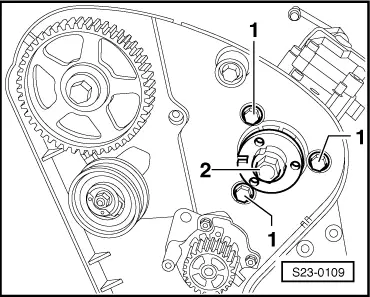
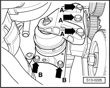
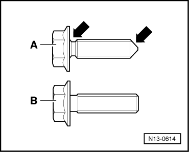
Version -A-: Fixing bolts with relief on the thread stem and tip -arrows-
–  Tighten the new fixing screws of the injection pump gear.
   Tightening torque: 20 Nm
  Note
t  After a dynamic test of the start of pump delivery tighten the fixing bolts a further 1/4 turn (90°).
t  The fixing bolts must be used once only as they are antifatigue bolts.
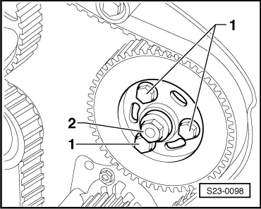
Version -B-: Fixing bolts without relief on the thread stem and tip
–  Tighten the old fixing screws of the injection pump gear.
   Tightening torque: 25 Nm
  Note
Do not replace the fixing bolts.
Continued for all versions:
–  Remove adjusting straightedge -MP 1-312- from the camshaft.
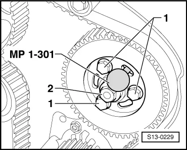
–  Pull out the rig pin -MP 1-301-.
–  Turn crankshaft two turns further in the direction of running of the engine and again position on TDC for cylinder 1.
–  Check whether
   the TDC marking on the flywheel,
the adjusting straightedge in the camshaft,
the rig drift in the injection pump gear,
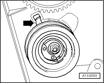
the setting of the tensioning pulley (notch/arrow)
   fits.
–  If the notch and arrow are not opposite one another, tighten the tensioning pulley and the fixing bolt to 25 Nm.
–  Turn crankshaft two turns further in the direction of running of the engine until the crankshaft is again on TDC for cylinder 1.
–  Repeat inspection.
–  Connect the injection lines, fuel feed line and electric wires.
  N13-0614
Fill the injection pump with diesel fuel as follows:
t  Screw in the adapter -V.A.G 1318/10- in the return-flow opening of the injection pump.
t  Connect the hand vacuum pump -V.A.G 1390 - to the adapter using a transparent plastic line of approx. 1 m.
t  Activate the vacuum pump until fuel flows out of the return-flow opening. Do not draw fuel into the vacuum pump.
t  Remove the adapter -V.A.G 1318/10- and close the fuel return-flow line.
–  Fit engine support bracket on the cylinder block.
   Tightening torque: 45 Nm
  A23-0005
–  Install engine mounting -arrows B- (replace fixing bolts).
   Tightening torque: 20 Nm + torque a further 90° (1/4 turn)
–  Screw engine mounting onto engine support bracket -arrows A- (replace fixing bolts).
   Tightening torque: 30 Nm + torque a further 90° (1/4 turn)
–  Install the cylinder head cover and the vacuum pump for the brake servo unit.
–  Install the noise insulation.
–  Dynamically test the commencement of injection of the injection pump and if necessary adjust → Chapter.
–  Install top toothed belt shield and engine cover.
  S13-0226

Testing components > < Removing