
Fabia Mk1
| Summary of components |
 WARNING
|
 Note
Note| t | If the earth strap of the battery was disconnected, pay attention to the sequence when connecting it → Electrical System; Rep. Gr.27. |
| t | The parts marked with an * must only be repaired in specialist service centres which have suitably trained personnel and are fitted out for working on the refrigerant circuit! |
| t | Comply with the safety measures when working on vehicles with air conditioning system and when using refrigerant R 134a and observe the instructions for working on the refrigerant circuit → Air conditioning system with refrigerant R134a; Rep. Gr.00 technical data. |

| 1 - | Defroster vent |
| q | integrated in dash panel |
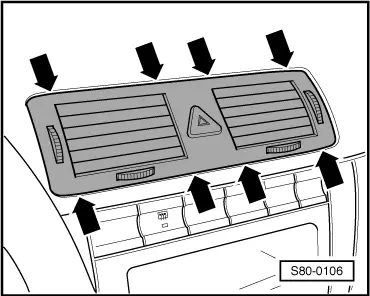
| 2 - | Centre dash panel vent |
| q | with warning light switch |
| q | removing and installing → Fig. |
| 3 - | Dash panel |
| q | Removing and installing → Body Work; Rep. Gr.70 |
| 4 - | Side window vent |
| q | carefully lever out with disassembly wedge -3409- |
| 5 - | Outer dash panel vent |
| q | use removal tool -3409- to carefully lever out at top and bottom (in the same way as for the centre dash panel vent) |
| 6 - | Intermediate piece for dash panel vents |
| q | attached to heater unit with clips |
| q | for removing, take out dash panel |
| 7 - | Centre part of dash panel |
| q | Removing and installing → Body Work; Rep. Gr.70 |
| 8 - | Module carrier |
| 9 - | Air conditioning unit* |
| q | Summary of components → Chapter |
| q | disassembling and assembling → Chapter |
| q | removing and installing → Chapter |
| 10 - | Right footwell vent |
| q | bolted to heater unit (1.5 Nm) |
| 11 - | Connection part for rear duct |
| 12 - | Rear duct |
| 13 - | End piece for rear duct |
| q | clipped into rear duct and seat cross member |
| 14 - | Ventilation frames |
| q | clipped into rear cross member ahead of spare wheel well from outside |
| q | sealing lips must operate freely and close automatically |
| q | area in front of ventilation frames must be clear otherwise ventilation of interior does not operate |
| 15 - | Left footwell vent |
| q | bolted to support (1.5 Nm) |
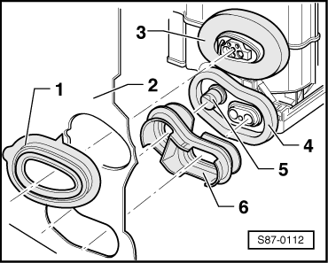
| 16 - | Gasket* |
| q | for connection of heat exchanger |
| q | in bulkhead (assembly plate) |
| q | Fitting position → Fig. |
| 17 - | Gasket* |
| q | for expansion valve connection |
| q | in bulkhead (assembly plate) |
| q | Fitting position → Fig. |
| 18 - | Air guide duct to the defroster vents |
| q | fitted onto heater unit and module carrier |
| q | for removing, take out dash panel |
|
|