| –
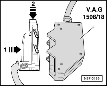
| Plug adapter cable -V.A.G 1598/18-A- into the multi-pin connector -arrow 1- and lock in -direction of arrow 2-. |
| The adapter cable -V.A.G 1598/18-A- allows to check the wiring according to the Current Flow Diagram. |
| –
| Set the correct measuring range on the measuring tool before connecting the measuring cables. Otherwise the electronic components may be destroyed! |
| t
| The indicated nominal values apply for an ambient temperature of 0 °C to 40 °C. |
| t
| If the measured values deviate from the nominal values, determine fault according to Current Flow Diagram. |
| t
| If the measured values only differ slightly from the nominal values, clean the bushes and plugs of the test devices and measuring cables and repeat test. Before replacing the relevant components check their wiring and connections. Specifically for nominal values below 10 Ω repeat resistance measurement on component. |
|
|
|