
Fabia Mk1
 Note
Note| t | Before installing heat the inner ring of the tapered-roller bearing to 100°C. |
| t | Replace both tapered-roller bearings together. |
| t | When replacing the tapered-roller bearing of the differential housing, gearbox housing or clutch housing adjust the differential → Chapter |
| t | Pos. 2 to 6 only applies for service. |
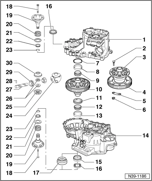
| 1 - | Gearbox housing |
| 2 - | Screw |
| 3 - | Differential housing |
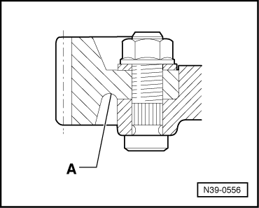
| q | screw to pinion for final drive |
| 4 - | Pinion for final drive |
| q | series riveted |
| q | screw → Fig. |
| q | heat to 100 °C before fitting |
| q | pressing off → Fig. |
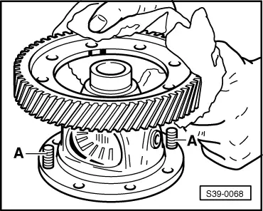
| q | Fitting position → Fig. |
| q | place on the differential housing → Fig. |
| q | is paired with the output shaft, replace together |
| 5 - | Shim |
| 6 - | Nut, 70 Nm |
| 7 - | Adjusting washer |
| q | for differential |
| q | Determine thickness → Chapter |
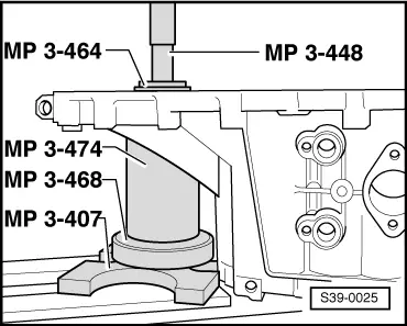
| 8 - | Outer ring/tapered-roller bearing |
| q | removing → Fig. |
| q | installing → Fig. |
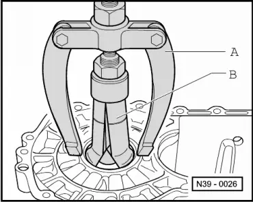
| 9 - | Inner ring/tapered-roller bearing |
| q | remove → Fig. |
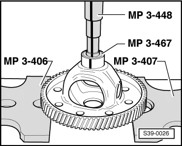
| q | pressing on → Fig. |
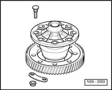
| 10 - | Differential housing |
| q | with riveted pinion for final drive |
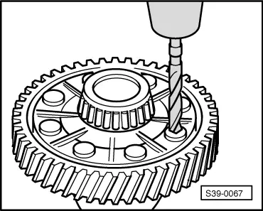
| q | when replacing the final drive pinion bore out the rivet heads → Fig. |
| q | Secure pinion for final drive → Fig. |
| 11 - | Drive wheel for speedometer |
| q | before pressing on the inner ring place it on the differential gear housing up to the stop |
| 12 - | Inner ring/tapered-roller bearing |
| q | remove → Fig. |
| q | pressing on → Fig. |
| 13 - | Outer ring/tapered-roller bearing |
| q | pressing out → Fig. |
| q | installing → Fig. |
| 14 - | Clutch housing |
| 15 - | Bushing |
| q | for support of gasket ring Pos. 16 |
| q | removing and installing → Chapter |
| 16 - | Gasket ring |
| q | left - replace with installed gearbox → Chapter |
| q | right - replace with installed gearbox → Chapter |
| 17 - | Bushing and gasket ring, single version |
| q | replace damaged gasket ring with bushing → Chapter |
| q | Difference → Chapter |
| 18 - | 25 Nm |
| q | screw to threaded connector Pos. 26 to attach the flange shaft |
| 19 - | Flange shaft |
| q | removing and installing → Chapter |
| 20 - | Pressure spring for flange shaft |
| q | fitted behind flange shafts |
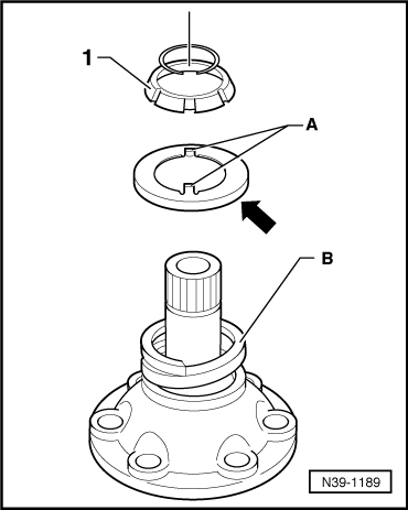
| 21 - | Thrust washer |
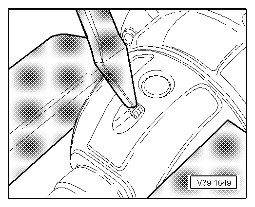
| q | Fitting position: flange to pressure spring, leg to conical ring |
| q | Fitting position of the changed thrust washer → Fig. |
| 22 - | Conical ring |
| q | with slots for thrust washer catch |
| q | Fitting position: Cone towards differential housing |
| 23 - | Retaining clip |
| q | holds the conical ring, stop disc and pressure spring in position when the flange shaft is removed |
| 24 - | Stop disc compound |
| q | insert with gear oil |
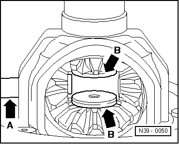
| 25 - | Differential bevel gear large |
| q | installing → Fig. |
| 26 - | Threaded part |
| q | installing → Fig. |
| 27 - | Differential bevel gear shaft |
| q | drive out with drift -MP 3-510- |
| q | installing → Fig. |
| 28 - | Tensioning sleeve |
| q | to secure the differential bevel gear shaft |
| q | removing and installing → Fig. |
| 29 - | Differential bevel gear small |
| q | installing → Fig. |
| 30 - | Differential bevel gear large |
| q | installing → Fig. |
|
|
|
|
Note
|

|
Note
|
|
|
|
|
|
Note
|
|
|
|
|
|
|
|
|
|
|
|
|
|
|
|