skoda Workshop Repair Guides

Skoda Workshop Service and Repair Manuals

Repairing the gearbox housing > < Disassembling gearbox
Assembling gearbox
Assembling gearbox
l  A new grooved ball bearing must be pressed onto the drive shaft → Chapter.
   
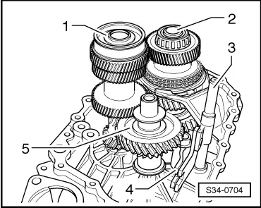
–  Insert the drive shaft -1-, the output shaft 5th/6th gear -2- together with gear shift rod -3-, shift fork -4- and reverse shaft -5-.
  S34-0704
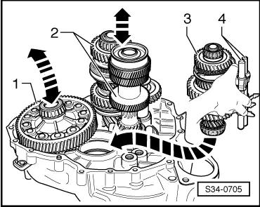
–  Insert the differential -1-.
  Note
For further installation of the shafts in the clutch housing a second mechanic is required.
–  Take the output shaft gears 1 through 4 -3- with the gear shift rods -4- in the right hand as shown.
–  Slightly lift the differential with the left hand.
–  At the same time the 2nd mechanic lifts the drive shaft, the output shaft 5th/6th gear and reverse gear -2- together with the reverse shaft.
–  Insert the output shaft gears 1 through 4 in -the direction of the arrow-.
l  The serrations of the drive shaft, output shafts and final drive/differential must be in mesh.
–  Place the shafts and the differential in their bearing assembly.
  S34-0705
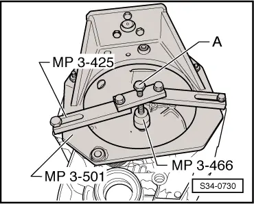
–  Secure the supporting bridge -MP3-425- for the drive shaft to the clutch housing.
  Note
To provide a clearer illustration, the clutch housing is shown at an angle of 180°.
–  Screw in screw -A- until the drive shaft is lifted slightly.
The gearbox housing is modified as of gearbox manufacturing date 10 04 6.
A washer is inserted above and below the grooved ball bearing for the drive shaft → Chapter.
  S34-0730
Top washerOuter diameter78.6 mm
Bottom washerOuter diameter85 mm

–  Check gearbox housing as follows:
   
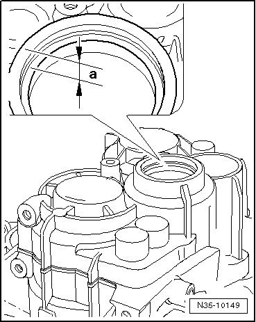
–  Measure the shoulder above the support for the grooved ball bearing dimension -a-.
The shoulder is chamfered deeper for the support of the washer.
  N35-10149
Shoulder above the grooved ball bearingDimension “a”Washer
as of gearbox manufacturing date 10 04 610.7 mmyes
up to gearbox manufacturing date 09 04 610 mmno

   
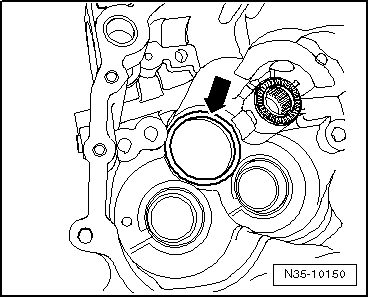
In the gearbox housing the bearing pedestal for the grooved ball bearing is also modified as of gearbox manufacturing date 10 04 6.
The bearing pedestal -arrow- for the grooved ball bearing (Pos. -2- ⇒ fig. N34-10816) is chamfered slightly deeper for the support of the washer (Pos. -1- ⇒ fig. N34-10816) .
  N35-10150
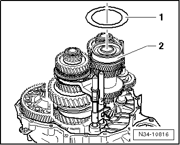
As of gearbox manufacturing date 10 04 6 place a washer (outside diameter = 85 mm) -1- onto the grooved ball bearing -2-.
–  Heat the gearbox housing with the -Heißluftgebläse- at the bearing assembly for grooved ball bearing/drive shaft to 100 °C for around 10 minutes.
–  Apply sealant -AMV 188 200 03- uniformly on the sealing surface.
  N34-10816
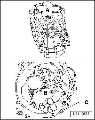
–  Fit gearbox housing and tighten new screws -A-, -B- and -C- to tightening torque → Chapter.
Assignment of screws:
A - Screw with captive washer
B - Screw without washer
C - Screw with captive washer
  N34-10565
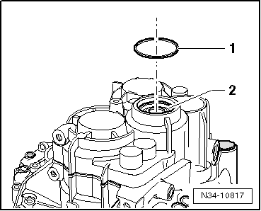
As of gearbox manufacturing date 10 04 6 place a washer -1- (outside diameter = 78.6 mm) above the grooved ball bearing -2-.
  N34-10817
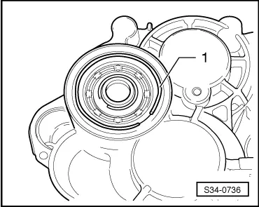
–  Install circlip -1- for grooved ball bearing/drive shaft.
–  Remove supporting bridge -MP3-425- for drive shaft.
  S34-0736
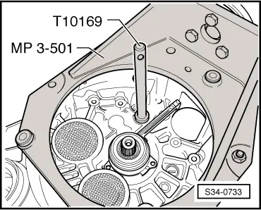
–  In case the serrated sleeve for the gearshift shaft was removed, drive it in with the drift -T10169- up to the stop of the tool.
–  Turn the gearbox with the opening for the gearshift shaft in the assembly stand upwards.
  S34-0733
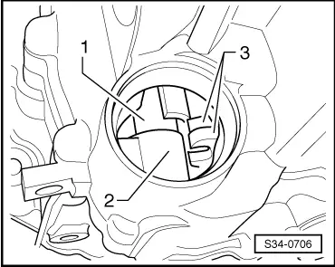
–  Insert the gearshift shaft -1- into the bottom bearing -2- and into the gearshift forks -3-. The cap in the illustration is removed for purposes of clear presentation.
  S34-0706
–  Press the gearshift shaft -1- against the serrated sleeve -2--direction of arrow- and guide with the shift finger -3- through the gearshift forks up to the stop downwards.
l  The gearshift cover -4- must be positioned at the same time parallel to the screw-on surface at the gearbox housing.
l  The gearshift shaft must slide easily into the selector movement (upwards and downwards).
  Note
If the gearshift cover is positioned obliquely to the screw-on surface, the gearshift shaft is not inserted into the bottom bearing.
  S34-0707
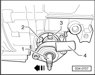
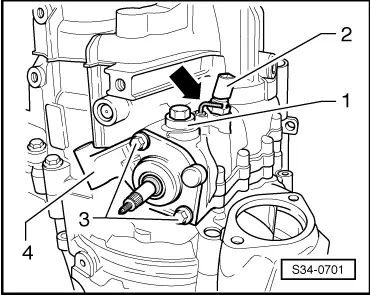
–  Tighten screws -3- for the cover/gearshift shaft -4- to tightening torque → Chapter.
–  Screw in locking screw -1-, at the same time the locking angle -arrow- must be laid out.
–  Install reversing light switch -2- and tighten to tightening torque → Chapter.
  S34-0701
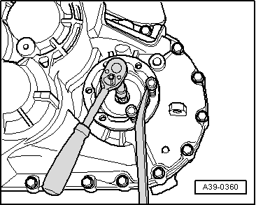
–  Install both flange shafts with pressure springs, stop discs and conical rings.
  A39-0360
–  Drive in the gasket ring for the drive shaft.
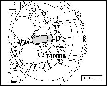
–  Mount slave cylinder with release bearing → Chapter.
  N34-1017
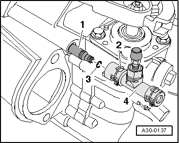
–  Insert new O-ring -3- at the connection -1- of the slave cylinder.
–  Press on the bleeder -4- at the connection of the slave cylinder until the retaining clip -2- clicks into place.
–  For checking pull at bleeder.
–  Shift through all gears consecutively.
  A30-0137
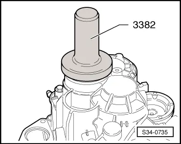
–  Drive the cap into the gearbox housing as far as the stop of the drift pin -3382-.
–  Remove gearbox from assembly stand.
  S34-0735

Repairing the gearbox housing > < Disassembling gearbox