
Fabia Mk1
 Note
Note
|

| 1 - | Top toothed belt guard |
| 2 - | Toothed belt |
| q | removing and installing, tensioning → Chapter |
| 3 - | 10 Nm |
| 4 - | 20 Nm + torque a further 45° (1/8 turn) |
| 5 - | 100 Nm |
| 6 - | Camshaft sprocket |
| 7 - | Hub |
| q | with rotor |
| q | to release and tighten use the counterholder -T10051- |
| q | to remove the extractor -T10052- use |
| q | removing and installing → Chapter |
| 8 - | Rear toothed belt guard |
| 9 - | Grommet |
| q | replace if damaged |
| 10 - | Camshaft position sensor -G40- |
| q | for removing, take the grommet → Chapter (Pos. 9) out of the rear toothed belt guard |
| 11 - | Cylinder head bolt |
| q | replace |
| q | pay attention to sequence for loosening and tightening → Chapter |
| q | if bearing caps of the camshaft are removed, insert special bases into the cylinder block before installing the cylinder head bolts → Chapter |
| 12 - | Bolt, 10 Nm |
| q | for engine cover |
| 13 - | Cylinder head cover |
| q | before fitting on, thoroughly clean sealing surface with a clean cloth |
| 14 - | to charge air pipe at the rear |
| 15 - | 10 Nm |
| q | tighten all bolts first of all by hand |
| q | Tighten crosswise from the inside outwards |
| 16 - | Pressure control valve |
| 17 - | Oil filler inlet |
| 18 - | Screw cap |
| 19 - | Sealing sleeve |
| q | replace if damaged |
| 20 - | Support |
| q | with fuel line |
| 21 - | Gasket for cylinder head cover |
| q | replace if damaged |
| 22 - | 20 Nm |
| 23 - | Lifting eye |
| 24 - | The unit injector |
| q | removing and installing → Chapter |
| 25 - | Mixing tube |
| q | inserted into cylinder head |
| q | pull out with hook |
| 26 - | Central plug connection |
| q | for pump-nozzle unit |
| 27 - | To the brake servo unit |
| 28 - | Tandem pump |
| q | for fuel and vacuum supply |
| q | removing and installing → Chapter |
| q | check → Chapter |
| 29 - | Intake hose |
| q | from fuel filter → Chapter |
| q | white marking |
| q | check for firm seating |
| q | secure with spring strap clamps |
| 30 - | Return-flow hose |
| q | for engine with identification characters AMF: to the fuel filter → Chapter |
| q | for engine with identification characters BNM, BNV: to the combination valve → Chapter |
| q | blue marking |
| q | check for firm seating |
| q | secure with spring strap clamps |
| 31 - | Gasket |
| q | replace |
| 32 - | Support |
| 33 - | Hexagon taper nut |
| 34 - | Cylinder head |
| q | removing and installing → Chapter |
| q | after replacing fill entire system with fresh coolant |
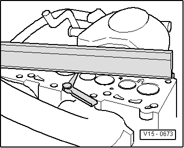
| q | Inspecting the cylinder head for distortion → Fig. |
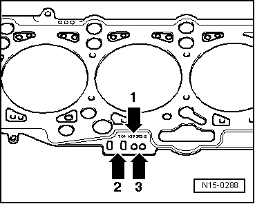
| 35 - | Cylinder head gasket |
| q | replace |
| q | Pay attention to the marking → Fig. |
| 36 - | Glow plug |
| q | 15 Nm |
| 37 - | Tensioning pulley |
| 38 - | 20 Nm + torque a further 45° (1/8 turn) |
Note
|
|