skoda Workshop Repair Guides

Skoda Workshop Service and Repair Manuals

Removing and installing sealing flange and flywheel > < Removing
Install timing belt and tension
l  Interlock camshaft with locking pin -MP1-301 (3359)-.
l  Lock the crankshaft with the crankshaft arrester -T10050-.
l  Interlock tensioning pulley with rig tool -T10265- and in the right end position with fixing nut.
  Note
t  Adjusting work on the timing belt must only be performed on a cold engine, as the position of the pointer at the tensioning element is temperature dependent.
   
t  Pay attention to correct fitting of the tensioning pulley in the rear toothed belt guard -arrow-.
  A13-0053
–  Turn camshaft sprocket in the slots clockwise in -direction of arrow- as far as the stop.
–  Fit timing belt onto crankshaft timing belt sprocket, tensioning pulley, camshaft sprocket and onto the coolant pump.
–  Install guide pulley → Chapter (Pos. 12).
–  Remove rig tool -T10265- from the tensioning pulley and loosen its fixing nut.
  S13-0265
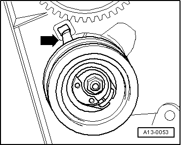
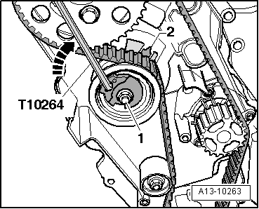
–  Turn the eccentric of the tensioning pulley with offset screwdriver -T10264- clockwise -arrow- in such a way until the pointer -2- stands in the centre of the base plate in the gap.
  Note
Ensure that the fixing nut of the tensioning pulley does not turn.
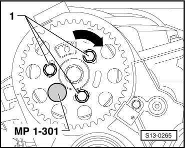
–  Hold the tensioning pulley in this position and tighten the fixing nut -1- of the tensioning pulley to 20 Nm + torque a further + 45° (1/8 turn).
  Note
When tightening the fixing nut, the pointer -arrow- turns max. 5 mm to the right from the gap of the base plate. This position must not be corrected, because the toothed belt settles when running-in.
  A13-10263
–  Position the counterholder -T10172- with bolt -T10172/4- at camshaft sprocket as shown and keep the camshaft sprocket under tension in -direction of arrow-.
–  Tighten fixing screws -1- of camshaft sprocket to 20 Nm + torque a further 45° (1/8 turn).
–  Remove rig pin -MP1-301 (3359)- and crankshaft arrester -T10050-.
Test timing
–  Turn the crankshaft 2 turns in the direction of running of the engine until the crankshaft is positioned shortly before TDC for cylinder 1.
  A13-0814
–  Interlock during this motion the hub in the direction of running of the engine with locking pin -MP1-301 (3359)-.
–  Check whether:
  S13-0404
t  the crankshaft can be interlocked with the crankshaft arrester -T10050-;
t  The pointer of tensioning pulley stands in the centre or max. 5 mm to the right from the gap of the base plate.
If the crankshaft cannot be arrested:
  N15-0446
–  Release the screws -arrows- of the camshaft sprocket.
  S13-0448
–  Rotate the crankshaft in direction of rotation of engine until the crankshaft can be arrested with the crankshaft arrester -T10050-.
  Note
If the crankshaft can be turned behind the TDC for cylinder 1, turn crankshaft back slightly and once again set to the TDC for cylinder 1 by turning in direction of rotation of engine.
–  Tighten fixing screws of camshaft sprocket to 20 Nm + torque a further 45° (1/8 turn).
–  Remove the locking pin -MP1-301 (3359)- and the crankshaft arrester -T10050-.
–  Turn crankshaft 2 turns in the direction of running of the engine until the crankshaft is again on TDC.
–  Repeat timing test → Anchor.
–  Further installation occurs in reverse order for removal, while paying attention to the following.
Tightening torque of engine mount → Chapter.
  N15-0446

Removing and installing sealing flange and flywheel > < Removing