| –
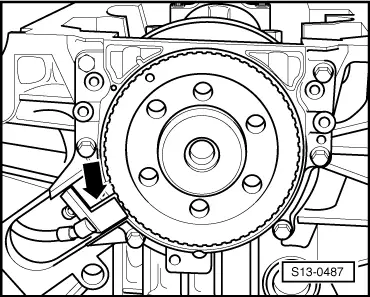
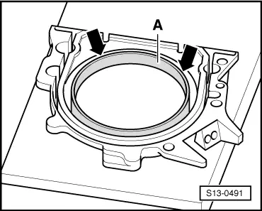
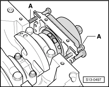
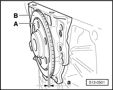
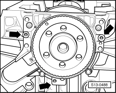
| Screw 3 screws M6x35 into the threaded bores of the sealing flange -arrows-. |
| –
| Press out sealing flange together with rotor from the crankshaft by alternately screwing the screws into the sealing flange. |

Note | t
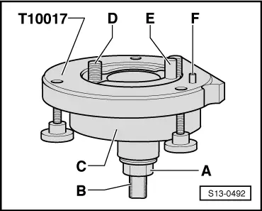
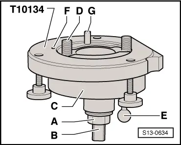
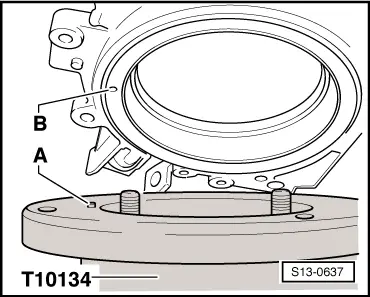
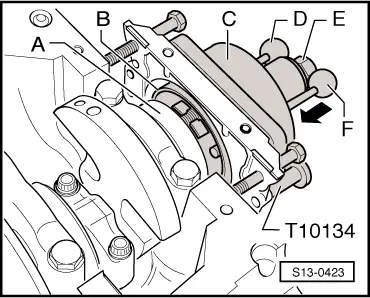
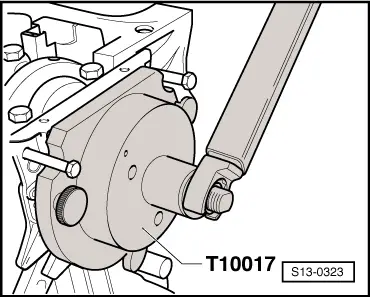
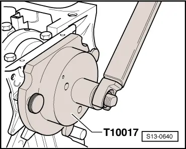
| On the 1.4/55 kW engine with identification characters BKY in combination with manual gearbox, the assembly device -T10134- is used for installing the sealing flange. In all other cases use the assembly device -T 10017-. |
| t
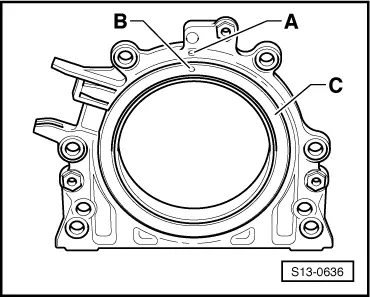
| New sealing flange is supplied from the spare parts with two gasket ring versions. The old versions of engines use an elastomer gasket ring with spring and the new engines have a PTFE gasket ring. |
| t
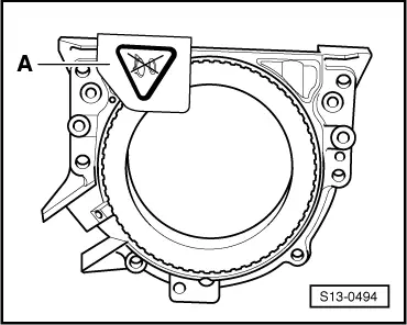
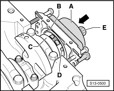
| The sealing flange with PTFE gasket ring is provided with sealing lip supporting ring. This supporting ring is intended as an assembly sleeve and must not be removed before installing. |
| t
| Do not separate or turn the sealing flange and rotor after removing them from the spare part package. |
| t
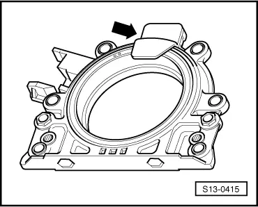
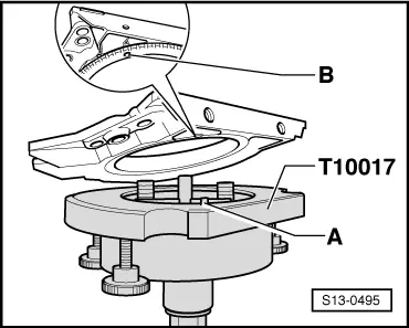
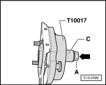
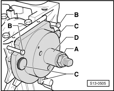
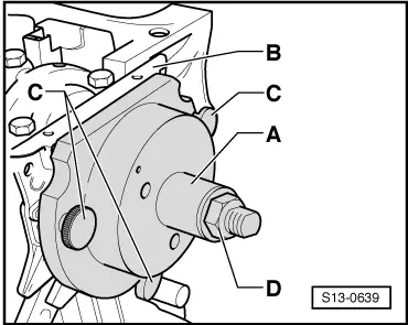
| The rotor is given its fitting location by positioning the assembly device -T 10017- or -T10134- to the positioning pin. |
| t
| The rotor has an elastomer layer on its sealing surface with the crankshaft. This layer must not be brought into contact with dirt or grease. |
| t
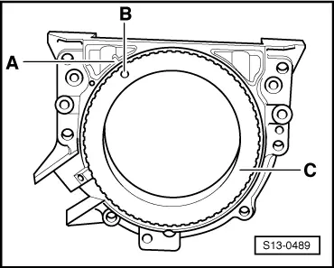
| The sealing flange and gasket ring form one unit and must be replaced together with the rotor. |
| t
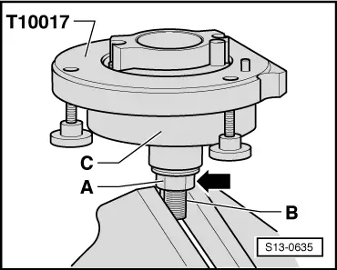
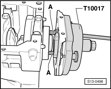
| The assembly device -T 10017- or -T10134- is given its fitting location to the crankshaft by means of a guide bolt, which is guided into the threaded bore of the crankshaft. |
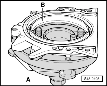
| A - Mounting the sealing flange with rotor on the assembly device -T 10017- or -T10134- |
|
|
|