
Fabia Mk1
| Valve gear - Summary of components |

| 1 - | 100 Nm |
| q | to release and tighten use the counterholder -T30004 (3415)- |
| 2 - | Camshaft sprocket |
| q | with sensor rotor for the Hall sensor -G163- |
| q | Installation position fixed by woodruff key -Pos. 4- |
| q | for removal and installation, remove toothed belt → Chapter |
| 3 - | Sealing ring |
| q | replace → Chapter |
| 4 - | Woodruff key |
| q | pay attention to correct position |
| 5 - | 20 Nm |
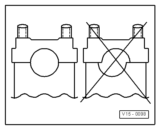
| 6 - | Bearing caps |
| q | Fitting position → Fig. |
| q | Mounting sequence → Chapter |
| q | Lightly coat contact surface for bearing cap 1 with sealant -AMV 174 004 01- |
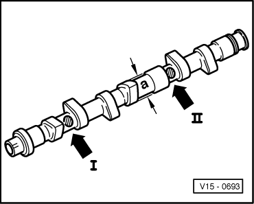
| 7 - | Camshaft |
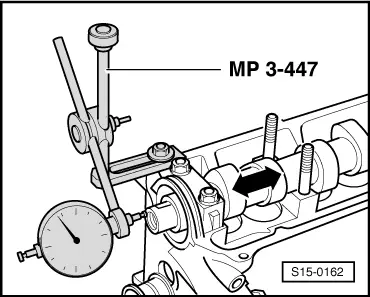
| q | Inspecting axial play → Fig. |
| q | removing and installing → Chapter |
| q | Slack: max. 0.01 mm |
| q | Identification → Fig. |
| 8 - | Bucket tappets |
| q | do not interchange |
| q | with hydraulic valve clearance compensation |
| q | check → Chapter |
| q | lay aside with contact surface facing down |
| q | before installing check axial play of the camshaft → Fig. |
| q | oil contact surface |
| 9 - | Collets |
| 10 - | Valve spring retainer |
| 11 - | Valve spring |
| q | removing and installing: |
| t | with cylinder head removed with -MP1-211 (VW 541/1a,/5)- and -MP1-213 (2036)- with valve supporting plate -MP1-218- |
| t | (with cylinder head installed) → Chapter |
| 12 - | Valve stem seal |
| q | replace → Chapter |
| 13 - | Valve guide |
| q | Repair of the guide with a collar |
| q | check → Chapter |
| q | replace → Chapter |
| 14 - | Cylinder head |
| q | removing and installing → Chapter |
| q | inspecting valve guides → Chapter |
| q | reworking valve seats → Chapter |
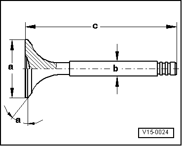
| 15 - | Valve |
| q | do not rework, only grinding in is permissible |
| q | Valve dimensions → Fig. |
|
|
 Note
Note
|
|
| Dimension | Inlet valve | Exhaust valve | |
| Ø a | mm | 39,5 ± 0,15 | 32,9 ± 0,15 |
| Ø b | mm | 6,92 ± 0,02 | 6,92 ± 0,02 |
| c | mm | 91,85 | 91,15 |
| α | ∠° | 45 | 45 |
|
|
| Cylinder 1 -arrow I- | E, or A |
| Cylinder 3 -arrow II- | 050 |