skoda Workshop Repair Guides

Skoda Workshop Service and Repair Manuals

Infotainment > < Checking the data BUS drive
Checking the data BUS Comfort version
  Note
t  In vehicles manufactured as of 08.2004, the LIN Bus wiring which is used between the door units is not connected with data BUS and therefore must not be disconnected during inspection.
t  Self-diagnosis, types and description of the convenience system → Body Work; Rep. Gr.01
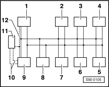
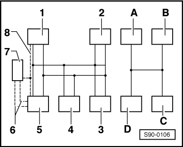
To test the data BUS Comfort version, first disconnect the connectors of all control units (central control unit for convenience system -J393-, climatronic control unit -J255-, door control unit rear right for convenience system -J389, door control unit rear left for convenience system -J388-, door control unit front passenger side for convenience system -J387, door control unit driver side for convenience system -J386-, control unit for the vehicle electric system -J519-). Only then is it possible to check the data BUS wiring for short circuits, for short circuits to earth, to positive terminal, if necessary for open circuit.
When working use the updated current flow diagrams → Current flow diagrams and Fitting locations.
   
Data BUS convenience system (vehicles manufactured up to 07.2004)
1 - Central control unit for convenience system -J393-
2 - Air conditioning control unit -J301-
3 - Door control unit rear right for convenience system -J389 -
4 - Door control unit rear left for convenience system -J388 -
5 - Door control unit front passenger side for convenience system -J387-
6 - Door control unit driver side for convenience system -J386-
7 - Control unit for traffic information over the radio -J559-
8 - Radio -R-
9 - Vehicle voltage control unit -J519-
10 - Data BUS, switched for new direct communicative generation of diagnostic units via Data BUS
11 - Diagnostic connection
12 - K cable
  S90-0105
Data BUS/LIN Bus convenience system (vehicles manfactured as of 08.2004)
Data BUS
1 - Central control unit for convenience system -J393-
2 - Air conditioning control unit -J301-
3 - Control unit for traffic information over the radio -J559-
4 - Radio -R-
5 - Vehicle voltage control unit -J519-
6 - Data BUS, switched for new direct communicative generation of diagnostic units via Data BUS
7 - Diagnostic connection
8 - K cable
LIN Bus
A - Door control unit rear right for convenience system -J389-
B - Door control unit rear left for convenience system -J388-
C - Door control unit front passenger side for convenience system -J387 -
D - Door control unit driver side for convenience system -J386-
Special tools and workshop equipment required
t  Hand multimeter (e.g. -V.A.G 1526 A -)
t  Adapter cable set (e.g. -V.A.G 1594 A -)
t  Current flow diagram
Test condition
l  Ignition off
Procedure
–  Remove the black 18-pin plug (T18a/XS2) from the Vehicle voltage control unit.
–  Connect the hand multimeter (e.g. -V.A.G 1526 A -) with cables from the Adapter cable set (e. g. -V.A.G 1594 A-) to contact 9 (CAN-L) and contact 12 (CAN-H) .
–  Check the data BUS wiring for short circuit.
If the nominal value is reached (there is no short-circuit between the cables):
–  Test data BUS cables for a short-circuit to the positive battery terminal or earth if necessary for interruption.
   Specified value: ∞ Ω
If the specified values are reached:
–  Proceed with test.
–  Re-connect all control units.
–  Interrogate fault memory of all control units.
If one of faults 1309, 1312, 1314, 1315, 1316, 1317, 1321 occurs:
–  Replace the relevant control unit (the relevant control units).
  S90-0106

Infotainment > < Checking the data BUS drive