skoda Workshop Repair Guides

Skoda Workshop Service and Repair Manuals

Repairing the front axle on vehicles as of CW 12 2008 > < Removing and installing anti-roll bar (up to CW 11 2008)
Removing and installing assembly carrier (up to CW 11 2008)
Special tools and workshop equipment required
t  Engine/gearbox jack with adapter, e.g. - V.A.G 1383- with -V.A.G 1359/2-
t  Wooden insert 490 x 270 x 50 mm for adapter -V.A.G 1359/2-
t  Fixing device -T10096-
t  Extractor -MP6-425 (3283)-
t  Polycarbamide grease -G 052 142 A2-
Removing:
  Note
Before commencing work, determine the measurement -a- → Chapter.
–  Removing the track control arm → Chapter.
   
–  Screw out the left and right nuts -1-.
–  Pull out left and right coupling rod -3- from stabilizer -2-.
–  Swivel the anti-roll bar upwards.
  S48-0113
–  Release the screws -1- and tie up power-steering gear with wire, so that it maintains its position.
–  Release the assembly carrier (align) and lower → Chapter (do not remove the universal joint of the steering column from the input shaft of the power steering).
  S40-0359
–  Remove anti-roll bar clamps -arrows-.
–  Take consoles out of the assembly carrier and remove assembly carrier.
Installing:
  Note
t  Observe the jointing and screw sequence of the screwed connections assembly carrier/track control arm → Item and assembly carrier/console/power-steering gear → Item.
t  The tightening of the screw for steering joint and assembly carrier can be performed, if the dimension -a- is maintained (vehicle in unladen condition - unladen weight position) → Chapter.
t  Before inserting the screws for fixing the assembly carrier, position the power-steering gear on the assembly carrier and tighten the screws for the power-steering gear.
–  Insert consoles into the assembly carrier.
  S40-0165
–  Screw clamps for anti-roll bar to consoles -arrows- and tighten.
–  Position the assembly carrier with engine/gearbox jack with adapter.
–  Raise the assembly carrier onto the fixing bolts and simultaneously fit the power steering gear onto the assembly carrier.
  S40-0165
–  Insert new screws -1- and tighten by hand.
–  Raise assembly carrier until the consoles rest on the body.
  Note
Check correct positioning of gasket for power steering gear onto the footwell opening of the vehicle.
  S40-0359
–  Tighten screws -1- of power steering gear/assembly carrier to specified tighening torque and remove attachment (suspension) of the power steering gear.
–  Screw assembly carrier to body → Chapter.
  S40-0359
–  Insert left and right coupling rod -3- into the stabilizer -2-.
–  Screw in the left and right nut -1- and tighten.
–  Installing the track control arm → Chapter.
  Note
It is necessary to perform a vehicle alignment in the event of → Chapter.
–  Perform a test drive.
–  Check the steering wheel position during the test drive.
  Caution
If after the test drive and with the front wheels pointing straight ahead the steering wheel is off straight, perform a chassis alignment → Chapter.
  S48-0113
Tightening torques:
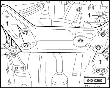
Power-steering gear to assembly carrier
t  Use new screws!
50 Nm + 90°
Console to body
t  Use new screws!
70 Nm + 90°
Support to body
t  Use new screws!
20 Nm + 90°
Console to assembly carrier
t  Use new screws!
50 Nm + 90°
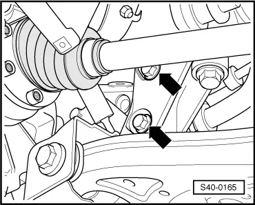
Pendulum support to gearbox
t  Use new screw!
30 Nm + 90°
Pendulum support to assembly carrier
t  Use new screw!
40 Nm + 90°
Twelve-point nut for securing the drive shaft to wheel hub
t  Use new nut!
t  Do not oil or grease the thread of the outer joint of the drive shaft.
50 Nm + 45°
Coupling rod to anti-roll bar40 Nm
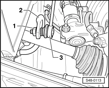
Steering joint to track control arm
t  Use new screws!
t  Use new lock washer!
20 Nm + 90°
Wheel bolts → Chapter


Repairing the front axle on vehicles as of CW 12 2008 > < Removing and installing anti-roll bar (up to CW 11 2008)