| Removing and installing rear suspension |
| Special tools, test equipment as well as aids required |
| Special tools and workshop equipment required |
| t
| Spring tensioning device, e.g. -V.A.G. 1752/1- |
| t
| Spring holder e.g. -V.A.G 1752/3- |
| t
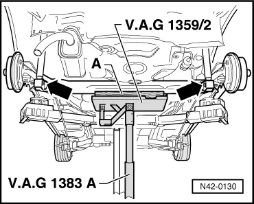
| Engine/gearbox jack with adapter, e.g. -V.A.G. 1383/A- with -V.A.G 1359/2- |
| t
| Wooden block 490 x 270 x 50 mm for attachment-V.A.G 1359/2- |
| t
| Tensioning strap, e.g. -T10038- |
| t
| Brake filling and bleeding device, e. g. -VAS 5234- |
| t
| Remove plugs for brake line |
| t
| Assembly paste -G 052 150 A2- |

Note | t
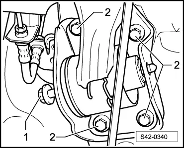
| Do not slacken the bracket for bonded rubber bush on body for the removal of the rear axle - only valid for vehicles up to MY 2010. |
| t
| The bracket for the right bonded rubber bush must be removed from the body for vehicles as of MY 2011. |
| t
| After removing and installing the bracket for bonded rubber bush, the overall track of the rear axle must be checked, adjusted if necessary. |
| t
| Before commencing work, determine the measurement -a- → Chapter |
| –
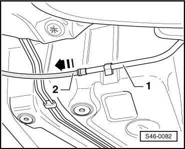
| Release the hand-brake. |
| –
| Actuate the brake pedal and insert the brake pedal load. |
| This prevents the brake line and the ABS hydraulic unit from running empty of brake fluid. |
|
|
|

 WARNING
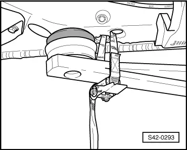
 Caution