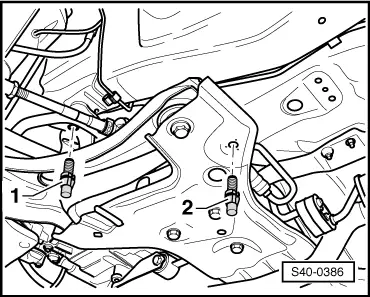
| Power-steering gear to assembly carrier | 50 Nm + 90° |
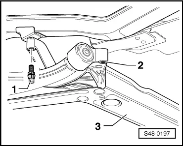
| Assembly carrier to body | 70 Nm + 90° |
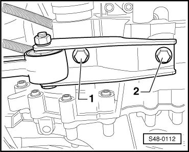
| Support to body | 20 Nm + 90° |
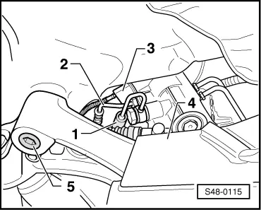
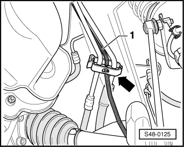
| Pendulum support to gearbox | 30 Nm + 90° |
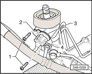
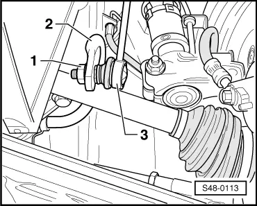
| Track rod end/track rod to steering arm | 20 Nm + 90° |
| power-assisted steering sensor -G250- to power-assisted steering gear TRW | 6 Nm |
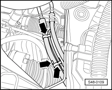
| Hollow screw for pressure line to power steering gear TRW (M14x1.5) | 35 Nm |
| Pipe screw for return line to power steering gear TRW (M16x1.5) | 30 Nm |
| Coupling rod to anti-roll bar | 40 Nm |
| Universal joint of the steering column to power-steering gear | 20 Nm + 90° |
| Wheel bolts | → Chapter |

 Note
Note
 Caution