Skoda Workshop Service and Repair Manuals
HOME
FEATURES
MENU
INDEX
ABOUT US
Enginecrankshaft group, pistons >
< Tightening torques
Fabia Mk2
Drive unit
1.2/47 kW; 1.2/51 kW Engine
Engine assy,cylinder block,crankcase / Removing and installing engine
Assembly bracket
Assembly bracket
Assembly bracket
Tightening torques
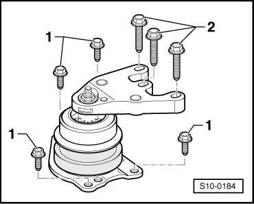
Unit mounting for engine
1 -
20 Nm + 90° (
1
/
4
turn) - replace
2 -
30 Nm + 90° (
1
/
4
turn) - replace
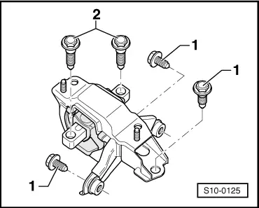
Unit mounting for gearbox
1 -
50 Nm + 90° (
1
/
4
turn) - replace
2 -
40 Nm + 90° (
1
/
4
turn) - replace
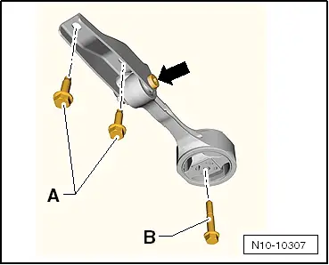
Pendulum support
Note
t
Position the screws
-A-
in the elongated holes of the pendulum support in such a way that there is maximum distance between the gearbox and the assembly carrier.
t
The screwed connection
-arrow-
must not be loosened.
A -
30 Nm + 90° (
1
/
4
turn) - replace
B -
40 Nm + 90° (
1
/
4
turn) - replace
Drive unit
1.2/47 kW; 1.2/51 kW Engine
Engine assy,cylinder block,crankcase / Removing and installing engine
Assembly bracket
Enginecrankshaft group, pistons >
< Tightening torques
 Note
Note