
Fabia Mk2
| Removing and installing fuel tank with attached parts and fuel filter ? 03.10 |
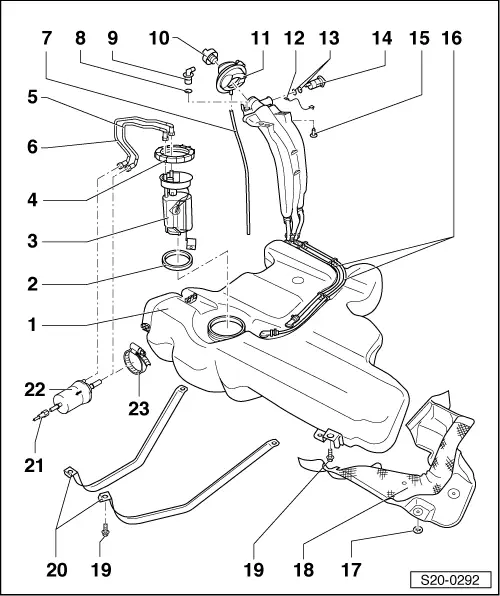
| 1 - | Fuel tank |
| q | support with engine/gearbox jack -V.A.G 1383 A - when removing |
| q | removing and installing → Chapter |
| q | after replacing the fuel tank, bleed → Chapter the fuel supply with the valve on the fuel strip |
| 2 - | Sealing ring |
| q | moisten with fuel before installing |
| q | replace if damaged |
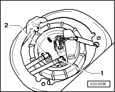
| 3 - | El. fuel delivery unit |
| q | removing and installing → Chapter |
| q | inspecting fuel pump → Chapter |
| q | Removing and installing the sender for fuel gauge display -G- → Chapter |
| q | Clean strainer if dirty |
| q | Fitting position of flange of el. fuel delivery unit → Fig. |
| 4 - | Union nut |
| q | use wrench for union nut - MP1-227 (3217)- for removing and installing → Chapter |
| 5 - | Return-flow line |
| q | between el. fuel delivery unit and fuel filter |
| q | blue |
| 6 - | Feed line |
| q | between el. fuel delivery unit and fuel filter |
| q | black |
| 7 - | Overflow hose |
| 8 - | O-ring |
| q | replace |
| 9 - | Gravity valve |
| q | to remove, unclip valve and lift up and out of the filler neck |
| q | inspect valve for blockage |
| q | Valve in a vertical position: open |
| q | Valve tilted 45°: closed |
| 10 - | Screw cap |
| 11 - | Fuel tank lid unit |
| 12 - | Earth connection |
| 13 - | O-ring |
| q | replace |
| 14 - | Vent valve |
| 15 - | 10 Nm |
| 16 - | Vent line |
| 17 - | Circlip |
| 18 - | Heat shield |
| q | for fuel tank |
| 19 - | 25 Nm |
| q | replace |
| 20 - | Tensioning strap |
| q | pay attention to different lengths |
| 21 - | Fuel feed line |
| q | black |
| q | to fuel rail at intake manifold |
| 22 - | Fuel filter |
| q | with integrated fuel pressure regulator 0.4 MPa (4 bar) |
| q | blue return-flow line in the middle and black feed line on the edge |
| q | after replacing the fuel filter, bleed → Chapter the fuel supply with the valve on the fuel strip |
| q | Fitting location: Pin at filter housing must engage in the recess of the guide for the fixing clamp |
| q | the direction of flow is marked by arrow |
| 23 - | Retaining clip |
| q | for fuel filter |
 Note
Note
|
|