skoda Workshop Repair Guides

Skoda Workshop Service and Repair Manuals

Removing and installing toothed belt (Roomster)|Install > < Removing and installing toothed belt (Roomster)
Removing
Removing
  Note
If the toothed belt is replaced when carrying out engine repair (apart from regular change interval), it should be entered in the Service Schedule!
Special tools and workshop equipment required
t  Locking pin -3359- or -MP1-301-
t  Supporting device -MP9-200 (10-222A)-
t  Small rig plate -T10008-
t  Crankshaft arrester -T10050- or crankshaft arrester -T10100-
t  Offset screwdriver -T10264-
t  Rig tool -T10265-
t  Pliers for spring strap clamps
t  Liquid locking material -D 000 600 A2-
–  Remove V-ribbed belt → Chapter.
–  Remove the front right wheelhouse liner → Body Work → Rep. Gr.66.
–  Remove belt pulley.
–  Remove middle and bottom toothed belt guard.
  WARNING
Fuel line is under pressure. Place cleaning cloths around the connection point before detaching hose connections. Reduce pressure by carefully removing the hose.
   
–  Disconnect the fuel feed line -1- and the fuel return-flow line -2-.
–  Remove expansion reservoir and place down to the front with coolant hoses connected.
–  Remove fuel filter from bracket and lay to the side at the point of the coolant expansion bottle.
  S13-0261
–  Install supporting device -MP9-200 (10-222A)- and support the engine with spindle -B- in fitting position. Allow spindle -A- to hang loosely.
  S13-0658
–  Remove engine mount -arrows-.
  Note
Releasing the pendulum support brings the engine slightly forwards and the engine mounting can be removed.
–  Unbolt the pendulum support from the gearbox.
–  Remove top toothed belt guard.
–  Lower the engine approx. 35 mm and release the bottom screw of the engine mounting.
–  Raise the engine approx. 45 mm relative to its normal position and release the top screws of the engine mounting.
  S13-0260
–  Swivel out the front engine mounting outwards and upwards -arrow A- and subsequently pull it out to the top at the rear -arrow B-.
–  Lower engine again into normal position.
  Note
Turn engine at hexagonal head of central screw at front end of the crankshaft, if necessary using counterholder -T10172- or using counterholder -MP1-216 (3036)- at camshaft sprocket.
–  Position crankshaft on TDC for cylinder 1.
  S13-0262
Engines with engine code AXR, BSW
l  The gear segment must point upwards.
l  The gap -1- between the pegs of the rotor of the camshaft position sensor must be opposite the marking “arrow 4Z”-2- on the rear toothed belt guard.
  Note
To provide a clearer illustration, the camshaft sprocket is illustrated without the toothed belt.
  A13-0349
Engines with identification characters BLS
l  The gear segment -arrow- must point upwards.
l  The lug -1- on the wheel of the camshaft position sensor must be opposite the marking -2- on the rear toothed belt guard.
  Note
To provide a clearer illustration, the camshaft sprocket is illustrated without the toothed belt.
For all vehicles
–  Lock hub with locking pin -3359- or -MP1-301-.
  S13-0568
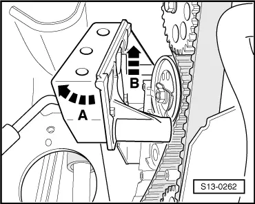
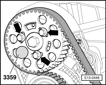
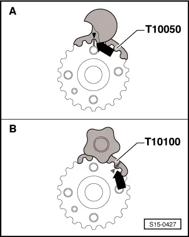
–  Depending on the version, lock the crankshaft toothed belt sprocket with the crankshaft arrester -T10050- or crankshaft arrester -T10100-.
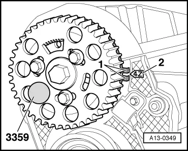
Version of the crankshaft toothed belt sprocket:
A = original version of toothed belt sprocket with circular tooth flanks, rectangular marking for TDC at tooth in 12 o'clock position - use crankshaft arrester -T10050-
B = new version of toothed belt sprocket with eliptical tooth flank, triangular marking for TDC at tooth opening in 1 o'clock position - use crankshaft arrester -T10100-
  Note
t  
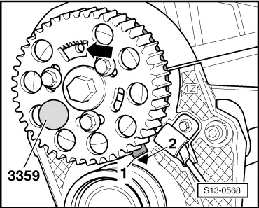
Markings on the toothed belt sprocket and on the crankshaft arrester must be in line with each other -arrow-. The stud on the crankshaft arrester must engage into the hole in the sealing flange.
t  The crankshaft arrester can only be fitted onto the serration of the toothed belt sprocket from the front side.
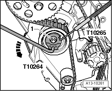
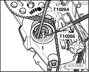
  Note
Mark the direction of rotation of the toothed belt with chalk or a felt-tip pen.
  S15-0427
–  Loosen the screws -arrows- of the camshaft sprocket.
  S13-0448
–  Loosen the fixing nut -1- of the tensioning pulley.
–  Carefully turn eccentric of the tensioning pulley in anti-clockwise direction -arrow- with offset screwdriver -T10264- until the tensioning pulley can be interlocked with rig tool -T10265-.
  A13-10261
–  Turn offset screwdriver -T10264- clockwise -arrow- as far as the stop and tighten fixing nut -1- by hand.
–  Remove guide pulley → Item.
–  First of all take toothed belt off crankshaft toothed belt sprocket and then from the other pulleys.
  A13-10262

Removing and installing toothed belt (Roomster)|Install > < Removing and installing toothed belt (Roomster)