skoda Workshop Repair Guides

Skoda Workshop Service and Repair Manuals

Securing the engine to the assembly stand > < Removing and installing engine
Removing
Removing
  Note
t  The engine is removed downwards together with the gearbox.
t  All cable straps that have been loosened or cut open when the engine was removed must be fitted again in the same locations when the engine is installed again.
t  Collect drained coolant in a clean container for reuse or proper disposal.
t  Jacking up points for raising the vehicle → Roomster .
–  Observe all safety measures and notes for assembly work on the fuel supply, injection and ignition system; as well as the rules for cleanliness → Chapter.
  WARNING
Observe measures when disconnecting the battery → Electrical System; Rep. Gr.27.
–  Remove battery and battery tray → Electrical System; Rep. Gr.27.
–  Remove air filter with air guide → Chapter.
–  Remove the sound dampening system → Body Work; Rep. Gr.50.
–  Remove the front wheelhouse liners → Body Work; Rep. Gr.66.
–  Drain coolant → Chapter.
–  Remove the coolant hoses from the radiator to the coolant regulator housing.
–  Pull off coolant hoses from heat exchanger for heating.
–  Detach coolant hoses from coolant expansion bottle.
–  Disconnect plugs from radiator fan -V7- and from thermoswitch for radiator fan -F18-.
   
–  Disconnect the fuel feed line -2- and the vent line -1- by pressing the latch clips.
–  Seal the lines in order to prevent any dirt from penetrating into the fuel system.
–  Remove the vacuum and ventilation hoses from the engine or from other components.
  S10-0213
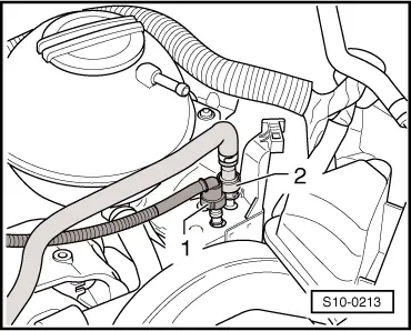
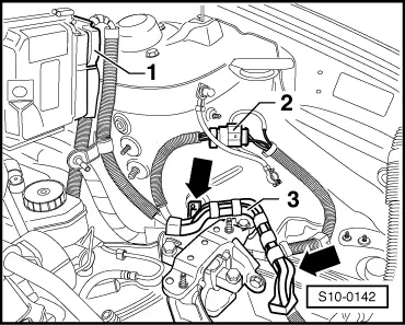
–  Unplug connector -1- from the engine control unit.
–  Unplug connector -2-.
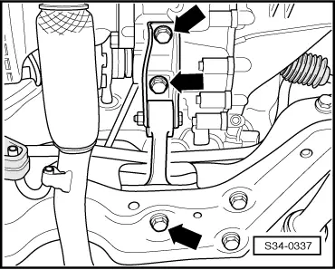
–  Unclip cable clip -3--arrows-.
The engine is removed together with the cable harness.
–  Disconnect all cables for the engine, gearbox and starter motor which will get in the way during removal.
Vehicles fitted with a manual gearbox
–  Remove shift mechanism from gearbox → Gearbox; Rep. Gr.34.
–  Remove slave cylinder → Gearbox; Rep. Gr.30.
  Note
Do not depress the clutch pedal.
Vehicles with automatic gearbox
–  Remove shift mechanism from gearbox → Automatic Gearbox; Rep. Gr.37.
Vehicles with air conditioning
  WARNING
Do not open the refrigerant circuit of the air conditioning system.
  Note
In order to avoid damage to the AC compressor as well as to the refrigerant lines and hoses, ensure that the lines and hoses are not over-tensioned, kinked or bent.
–  Remove V-ribbed belt → Chapter.
–  Remove AC compressor from holder → Heating, Air Conditioning; Rep. Gr.87.
–  Secure the air-conditioning compressor with attached lines to the assembly carrier.
Continued for all vehicles
–  Remove exhaust pipe.
t  Vehicles with engine identification characters BTS: → Chapter
t  Engine identification characters CFNA: → Chapter
  S10-0142
–  Unbolt the pendulum support -arrows-.
–  Unscrew drive shaft to the right and left of the gearbox and tie up → Body; Rep. Gr.40.
  S34-0337
–  First of all tighten the bolt of the engine mount - T40075 A- at the front on the engine.
  S10-0453
–  Position the engine mount -T40075 A- in the engine/gearbox jack -V.A.G 1383 A-.
–  Tighten engine mount -T40075 A- at the bolt.
–  Screw engine mount -T40075 A- onto cylinder block reverse side to 20 Nm -arrows-.
–  Slightly raise the engine/gearbox unit.
  Note
Use double ladder to release the screws for the assembly bracket -VAS 5085-.
For vehicles with assembly bracket version 1
  S10-0454
–  Unscrew bolts -1-.
For vehicles with assembly bracket version 2
  S10-0182
–  Unscrew nut -3- and disconnect earth lead from engine mount.
–  Unscrew bolts -2-.
For all vehicles
  S10-0452
–  Unscrew screws -arrows- and remove gearbox mount.
  Note
t  Check whether all hose and line connections between engine, gearbox and body are released.
t  When lowering carefully guide the engine/gearbox assembly, in order to avoid damage.
–  Pull engine/gearbox unit as far forward as possible and lower slowly downwards.
  S10-0120

Securing the engine to the assembly stand > < Removing and installing engine