skoda Workshop Repair Guides

Skoda Workshop Service and Repair Manuals

Measuring the axial play of the camshafts > < Removing and installing gasket ring for camshaft
Removing and installing camshafts
Special tools and workshop equipment required
t  Counterholder -T10051-
t  Extractor -T10052-
t  
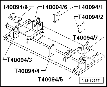
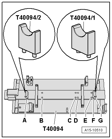
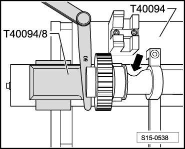
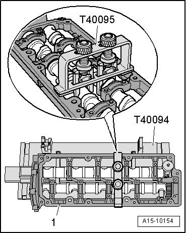
Camshaft-insertion tool -T40094-
t  Camshaft-insertion tool -T40095-
t  
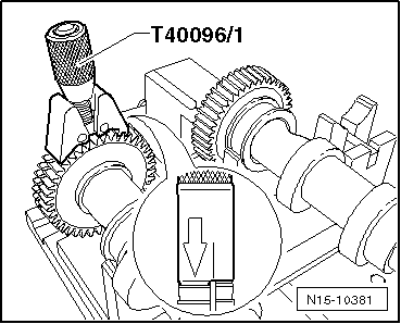
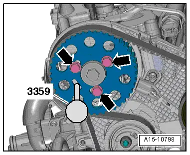
Tensioning tool -T40096/1-
t  
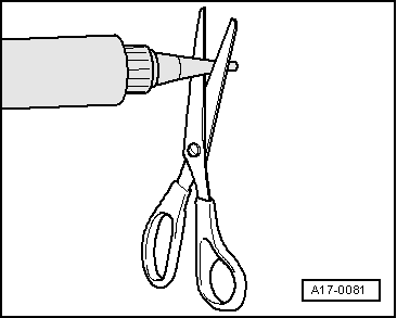
Silicone sealant -D 176 501 A1-
t  Sealant remover gasket stripper (bearing code GST, bearing article no. R 34402), manufacturer Retech s.r.o.
t  Cleaning and degreasing agent, e.g. -D 009 401 04-
t  Protective goggles and gloves
Removing
l  Cylinder head fitted.
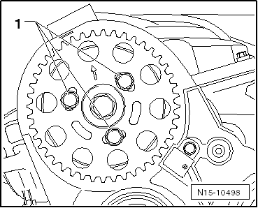
–  Pull toothed belt off camshaft sprocket and from toothed belt gear on the high pressure pump → Chapter.
–  Remove cylinder head cover → Chapter.
   
–  Screw out the fixing screws -1- of the camshaft sprocket.
–  Remove camshaft sprocket from the hub.
  N15-10498
–  Slacken screw -1- for the hub of the camshaft, to do so counterhold with counterholder -T10051-.
–  Release screw by about 2 turns.
  N15-0271
–  Position the extractor -T10052- at the hub of the camshaft and screw the screws -1- into the hub.
–  Slacken the hub of the toothed belt sprocket from the camshaft cone by uniformly tightening the screw of the extractor -2-.
  Note
While doing so, hold the extractor firmly using a wrench SW 30.
–  Remove hub of toothed belt sprocket from cone of camshaft.
–  Remove vacuum pump → Chapter.
  N15-0280
–  Loosen the screws for the bearing frame in the sequence -20...1-.
–  Unscrew screws and carefully separate the bearing frame from the cylinder head.
–  Mark the camshafts for reinstalling and remove.
Install
  WARNING
Wear protective gloves when working with sealant and grease remover!
–  Remove residual sealant on the bearing frame and cylinder head using a chemical sealant remover.
–  Clean sealing surfaces, they must be free of oil and grease.
–  Oil contact surfaces of camshafts.
  Caution
The camshafts must only be installed using the camshaft-insertion tool -T40094- as described below. Otherwise the axial bearing in the bearing frame can be destroyed and the cylinder head must be replaced.
Set up the camshaft-insertion tool -T40094- as follows:
  N15-10533
–  Remove the supports -T40094/3-, -T40094/4- and -T40094/5- from the base plate. The screws are located at the bottom.
  Note
If the components of the camshaft-insertion tool -T40094- are not yet marked, they must be marked for the subsequent refitting. For this use e.g. blow counts.
  N15-10377
–  Tighten the supports -T40094/9- and -T40094/12- (with detent bracket -T40094/11-) to the base plate as shown in the illustration.
  N15-10544
–  Place the support -T40094/2- on the position -A- and the support -T40094/1- on the position -D-.
–  Insert the inlet camshaft in the supports -T40094/1- and -T40094/2-.
  A15-10510
l  The recess -arrow- for the cylinder head screw must point to the outside.
–  Fit on a feeler gauge of 0.50 mm and slide the support -T40094/8- into the groove of the inlet camshaft.
–  Insert the outlet camshaft in the supports -T40094/9- and -T40094/12- and lock with serration of detent bracket -T40094/11-
l  The peg on the detent bracket -T40094/11- must engage in the groove of the camshaft.
  S15-0538
–  Position the tensioning tool -T40096/1- on the pinions of the outlet camshaft in such a way that each clamping arm engages in a pinion.
l  The wider clamping arm must engage in the wider pinion.
–  Tension the tensioning tool -T40096/1- with the knurled wheel until the tooth flanks of both wheels are aligned.
–  Slide the outlet camshaft to the inlet camshaft until the serrations are in mesh.
  N15-10381
–  Position the bearing frames onto the camshafts.
l  All of the camshaft bearings must rest on the camshafts.
–  Position the camshaft-insertion tool -T40095-, as shown in the figure, and fix the camshafts in the bearing frame.
–  Remove the detent bracket -T40094/11- and pull the support -T40094/8- out of the groove of the inlet camshaft.
  Note
  A15-10154
Pay attention to the use by date on sealant.
–  Cut off nozzle tube at the front marking (Ø of nozzle approx. 2 mm).
  Caution
Risk of contamination of the camshaft bearings through excess sealant.
Do not apply thicker sealant beads than indicated.
  A17-0081
–  Apply sealant onto the clean sealing surface of the cylinder head as shown in the illustration.
l  Thickness of the sealant beads: 2…3 mm
l  Pay attention that the oil supply hole for the bearing frame is not closed through excess sealant.
  Note
The bearing frame with camshafts must be installed within 5 minutes after applying the silicone sealant.
–  Remove the camshafts together with the bearing frame, the camshaft-insertion tool -T40095- and the tensioning tool -T40096/1- from the camshaft-insertion tool -T40094- and carefully insert into the bearings in the cylinder head.
  N15-10534
–  Insert the screws of the bearing frame and first tighten in the sequence -1 … 20- by hand.
l  The ladder frame must rest on the cylinder head with its complete contact surface.
–  Tighten the screws of the bearing frame in the sequence -1…20-.
   Tightening torque: 10 Nm
–  Remove the camshaft-insertion tool -T40095- and the tensioning tool -T40096/1-.
The further assembly is carried out in the reverse order, while paying attention to the following:
–  Drive the new screw cap ( → Chapter, Pos. 17) into the cylinder head until flush.
–  Replacing camshaft gasket ring → Chapter.
  N15-10533
–  Install the hub for the camshaft timing gear and tighten the screw -1- to 100 Nm. To do so, counterhold with counterholder -T10051-.
  N15-0271
–  Push camshaft sprocket onto the hub.
  Note
While doing so, the arrow on the camshaft sprocket must be close to the »12 o'clock« position.
–  Screw in screws -1- by hand.
  N15-10498
–  Lock hub with locking pin -3359-.
–  Installing the timing belt → Chapter.
–  Install vacuum pump → Chapter.
–  Install cylinder head cover → Chapter.
  Note
t  After installing the camshafts, the engine must not be cranked or started for about 30 minutes. The hydraulic clearance compensation elements must settle (otherwise the valves would strike the pistons).
t  After carrying out work on the valve gear, carefully crank engine at least 2 revolutions to ensure that no valve touches the piston when the engine is started.
  A15-10798

Measuring the axial play of the camshafts > < Removing and installing gasket ring for camshaft