skoda Workshop Repair Guides

Skoda Workshop Service and Repair Manuals

Removing and installing sealing flange and flywheel > < Balancing shaft module - Summary of components
Removing balancing shaft module
Special tools and workshop equipment required
t  Rig pin -T40011-
t  Socket insert -T10061-
Removing
–  Removing toothed belt → Chapter.
–  Removing the oil pan → Chapter.
–  Remove the sealing flange on the belt pulley side → Chapter.
–  Remove cover of balancing shaft module.
   
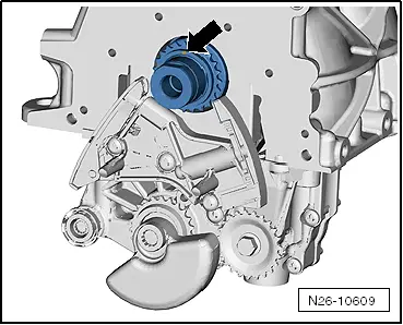
–  Lock the chain tensioner with the rig pin -T40011--arrow-.
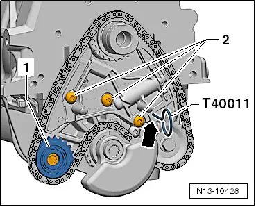
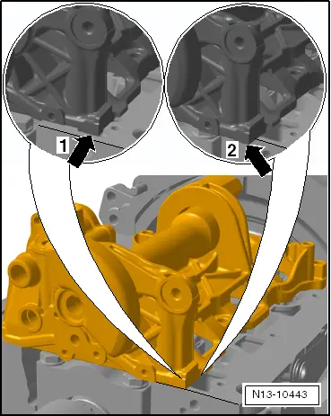
–  Release screw from deflection chain sprocket -1- and remove deflection chain sprocket.
–  Release screws -2- from chain tensioner and remove chain tensioner.
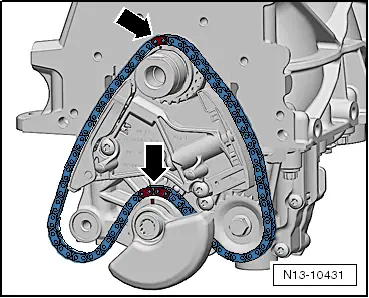
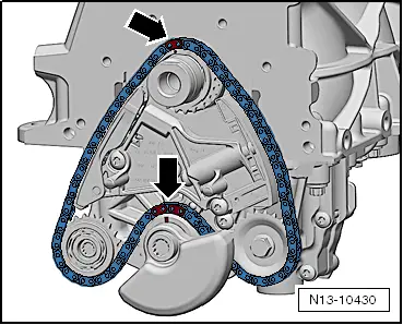
–  Remove chain from chain sprockets and place on a clean surface.
–  Unscrew balancing shaft module from cylinder block and place down on a clean surface.
Install
–  Check all the components of the chain drive for wear.
  Note
When installing the balancing shaft module, ensure that the dowel sleeve is inserted in the cylinder block and the O-ring in the balancing shaft module.
–  Position the balancing shaft module on the cylinder block.
  N13-10428
–  Align the balancing shaft module in such a way that it is flush with the outer edge of the cylinder block on the belt pulley side.
  Caution
Under no circumstances the balancing shaft module must be installed as shown in the picture detail with -arrow 1 and 2-.
–  Screw in the new screws of the balancing shaft module and tighten crosswise from the inside outwards in several stages.
   Tightening torque: 14 Nm + torque a further 180° (1/2 turn)
–  Clean the chain with a non-fluffing cleaning cloth.
  N13-10443
–  Check, if the marking -arrow- at the chain sprocket of the crankshaft is nearly located at the top.
  N26-10609
–  Fit the chain onto the chain sprockets of the crankshaft, the oil pump and the balancing shaft as shown.
Conditions
l  The marking on the chain sprocket of the crankshaft -top arrow- must be opposite the individual colour-marked chain link.
l  The marking on the chain sprocket of the balancing shaft -bottom arrow- must be between both colour-marked chain links.
l  The colour markings which are only located on one side of the chain locks must point to the outside. Thus the original direction of rotation of the chain is ensured.
  N13-10431
–  Insert the deflection chain sprocket -2- into the chain and tighten at the balancing shaft module to 23 Nm.
–  Install chain tensioner.
–  Screw in screws -2- and tighten to 16 Nm
–  Remove the rig pin -T40011- from the chain tensioner.
  N13-10428
–  Check if the markings on both chain sprockets are correctly positioned to the marked chain links -arrows- → Anchor.
Further installation occurs in a similar way in reverse order to removal.
  N13-10430

Removing and installing sealing flange and flywheel > < Balancing shaft module - Summary of components