skoda Workshop Repair Guides

Skoda Workshop Service and Repair Manuals

Securing the engine to the assembly stand > < Removing and installing engine trim panel
Removing engine
Removing engine
(Fabia II, Roomster, Rapid)
Special tools and workshop equipment required
t  Engine mount -T10012-
t  
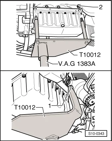
Engine/gearbox jack, e.g. -V.A.G 1383 A-
t  Catch pan, e.g. -VAS 6208-
t  Step ladder
t  
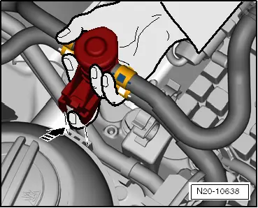
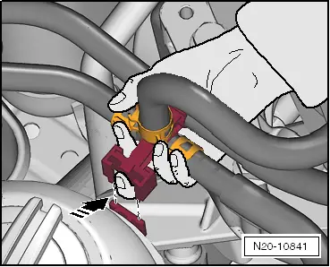
Pliers for spring strap clamps
  Note
t  
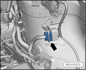
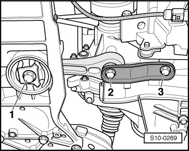
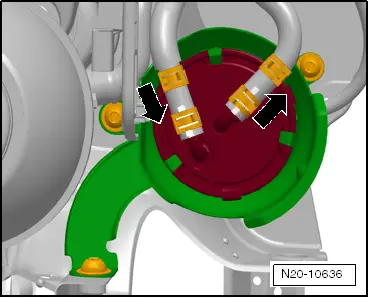
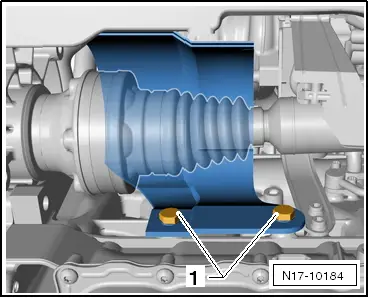
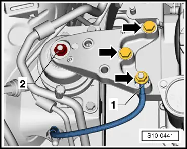
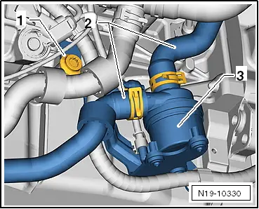
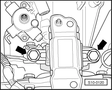
If the partial engine must be replaced after the engine was removed, check whether the clamping claws for the injection units on the new partial engine were tightened. Tightening torque: Position 2 → Chapter.
t  The engine is removed downwards together with the gearbox.
t  All cable straps that have been loosened or cut open when the engine was removed must be attached again in the same location when the engine is installed again.
t  Collect drained coolant in a clean container for proper disposal or reuse.
  Caution
When undertaking all installation work, particularly in the engine compartment due to its cramped construction, please observe the following:
t  Lay lines of all kinds (e.g. for fuel, hydraulic fluid, cooling fluid and refrigerant, brake fluid, vacuum) and electrical lines in such a way that the original line guide is re-established.
t  In order to avoid damage to the cables, ensure that there is adequate free access to all moving or hot components.
Observe all safety measures and notes for assembly work on the fuel supply and injection system, at the charge air system and observe as well the rules for cleanliness → Chapter.
–  If present, take the adapter for the anti-theft wheel bolts out of the luggage compartment.
–  Remove front wheels → Chassis; Rep. gr.44.
–  Disconnect the battery-earth strap with the ignition off → Electrical System; Rep. gr.27.
–  Remove engine cover → Chapter.
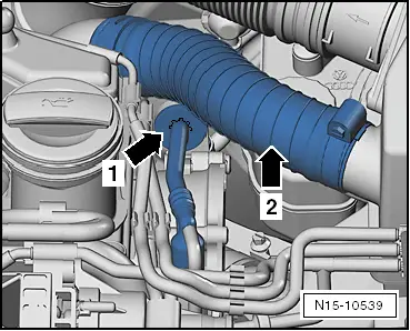
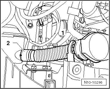
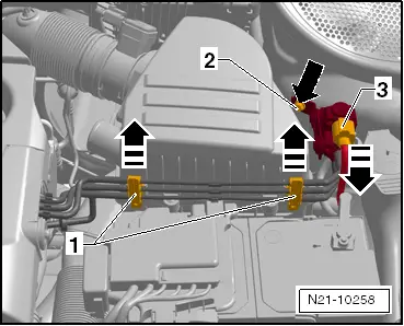
–  Remove air filter housing with air mass meter -G70- and intake hose → Chapter.
–  Remove battery and battery tray → Electrical System; Rep. gr.27.
   
–  Release plug -3- from charge pressure control solenoid valve -N75-.
–  Unscrew charge pressure control solenoid valve -N75 - with fixture -2- and place it on the engine.
–  Remove shift mechanism from gearbox → Gearbox; Rep. gr.34.
–  Remove the clutch slave cylinder from the gearbox → Gearbox; Rep. gr.30.
  WARNING
After removing the slave cylinder, do not depress the clutch pedal.
For vehicles Fabia II, Roomster
  N21-10258
–  Remove the vacuum hose -arrow- from the brake servo unit.
For vehicles Rapid
  A10-10031
–  Separate the vacuum line behind the bracket at the cylinder head -arrow 1-.
  N15-10539
–  Disconnect the plug connection -1- for the exhaust gas temperature sender 1 -G235- and loosen from the bracket.
Continued for all vehicles
–  Unlatch the fuse and disconnect the front plug from the engine control unit → Chapter.
  N26-10756
–  Disconnect plug connection -arrow-.
  N10-10373
–  Carefully slacken the engine wiring harness on its fixing points -arrows-.
–  Place the engine wiring harness on the engine.
  N10-10371
–  Unscrew the positive cable to the generator -1-, unclip and place on the gearbox.
–  Unscrew the cable from the starter and the gearbox and remove it.
  N10-10372
–  Release screws -1 ... 3- and remove pendulum support.
For vehicles Fabia II, Roomster
–  Remove pre-exhaust pipe with diesel particle filter → Chapter.
For vehicles Rapid
–  Remove pre-exhaust pipe with catalytic converter, while doing so remove the assembly carrier → Chapter.
Continued for all vehicles
  S10-0269
–  Separate fuel feed line -2- and fuel return-flow line -1-, to do so press the release buttons. Unlock the quick coupling and disconnect → Chapter.
–  If necessary, collect the fuel which flows out with a cloth.
For vehicles Fabia II, Roomster
  A20-1118
–  Unlock the catch peg with a finger and pull the fuel preheating valve upwards out of the guide of the coolant expansion bottle.
For vehicles Rapid
  N20-10638
–  Unlock the catch peg with a finger and pull the T-piece upwards out of the guide from the coolant expansion bottle.
Continued for all vehicles
  N20-10841
–  Push the catch pegs up and remove the fuel filter towards the top.
–  Place the fuel filter and the fuel hoses together with the fuel preheating valve on the engine.
–  Remove fuel filter bracket.
–  Remove the right and left wheelhouse liner → Body Work; Rep. gr.66.
  N20-10636
–  Unscrew the nuts from the right steering joint -arrows- and press the steering joint out of the suspension arm.
  S40-0262
–  Unscrew screws -1- of protective plate for right drive shaft, if present.
–  Remove right drive shaft from gearbox and secure with wire → Chassis; Rep. gr.40.
–  Remove left drive shaft from gearbox → Chassis; Rep. gr.40.
  N17-10184
–  Unscrew the nut from the left coupling rod -2- and press off the coupling rod from the anti-roll bar.
–  Unscrew the nuts from the left steering joint -3- and press the steering joint out of the suspension arm.
  S10-0399
–  Unscrew the nut -2- from the front left track control arm on installed front left vehicle level sensor -G78-.
–  Turn the wheel bearing housing to the left up to the stop.
–  Swivel the steering joint outwards and secure the drive shaft -1- with a band -A- in the wheelhouse.
–  Remove right charge air hose.
  S40-0395
–  Release screws -arrows-.
–  Loosen hose clamp -2-.
–  Disconnect the plug -1- at the charge pressure sender -G31- with intake air temperature sender -G42- and remove the right charge air pipe.
–  Drain coolant → Chapter.
–  Remove the remaining coolant hoses from the radiator.
  S13-0738
–  Remove the earth connection -1- from the assembly bracket.
–  Remove coolant expansion bottle and place on the engine.
  S10-0441
–  Unclip the filler neck of the windshield washer reservoir -1- and lay to the side.
On vehicles with air conditioning
–  Remove alternator → Electrical System; Rep. gr.27.
  WARNING
Risk of injury through refrigerant.
Do not open the refrigerant circuit of the air conditioning system.
  Caution
Risk of damaging the condenser as well as the refrigerant lines and hoses.
Do not over-tension, buckle or bend refrigerant lines and refrigerant hoses.
–  Remove the AC compressor from the bracket for auxiliary units → Heating, Air Conditioning; Rep. gr.87.
  N10-10296
–  Attach the AC compressor -3- e.g. behind the lock carrier as shown in the figure. As protection put a sheet of cardbord -1- on the radiator wall.
Continued for all vehicles
  S10-0370
–  Remove noise insulation of oil pan -1-, to do so slacken the fixing parts -arrows-.
  A17-10410
–  Unscrew screw -1- and push the coolant recirculation pump 2 -V178--3- to the side.
–  Disconnect further necessary plug connections at the engine and gearbox or line connections to engine and gearbox.
  N19-10330
–  Separate the quick couplings -arrows- at the heat exchanger.
–  Unclamp all remaining connecting, coolant, vacuum and suction hoses from the engine.
–  Release all remaining plugs at engine and gearbox and lay aside the relevant lines.
  N10-10279
–  Screw engine mount -T10012- to the cylinder block with nut -2- and screw -1- to 20 Nm.
–  Insert engine/gearbox jack -V.A.G 1383 A- in the engine mount and slightly raise.
  Note
Use double ladder to release the screws for the engine/gearbox mounting.
For vehicles Fabia II, Roomster
  S10-0343
–  Release the screws which connect the engine mount with the engine support -arrows-.
For vehicles Rapid
  S10-0441
–  Unscrew engine mounting and remove completely -arrows-.
Continued for all vehicles
  N10-10536
–  Remove the assembly bracket at the gearbox. Release screws -arrows-.
  Note
t  Check whether all hose and line connections between engine, gearbox and body are released.
t  When lowering carefully guide the engine with the gearbox, in order to avoid damage.
t  Ensure the necessary space for lowering the assembly by pressing off the assembly carrier.
–  Carefully lower engine with gearbox. During this procedure, turn or move the engine with the gearbox depending upon the constriction.
–  Remove the gearbox from the engine.
  S10-0120

Securing the engine to the assembly stand > < Removing and installing engine trim panel