skoda Workshop Repair Guides

Skoda Workshop Service and Repair Manuals

Removing and installing V-ribbed belt for vehicles with air conditioning system and tensioning element > < Removing and installing V-ribbed belt for vehicles without air conditioning system
Removing and installing V-ribbed belt for vehicles with air conditioning system and guide pulley
(Fabia II, Roomster, Octavia II, Superb II, Yeti)
Removing
–  Remove the sound dampening system → Body Work; Rep. gr.50.
For vehicles Fabia II, Roomster
–  Removing the right wheel-well inner panel → Body Work; Rep. gr.66.
   
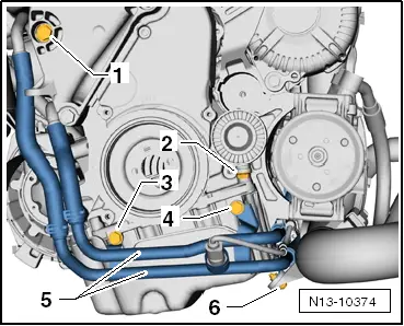
–  Release screws -3, 4, 6-.
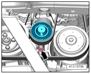
–  Carefully push the coolant line -5- to the side so that there is adequate space for loosening the screw -2- for the guide pulley of the V-ribbed belt.
For vehicles Octavia II, Superb II, Yeti
–  Remove the right wheelhouse liner bottom part → Body Work; Rep. gr.66.
For all vehicles
  Caution
Risk of damage through reversing the rotation direction of an already used V-ribbed belt.
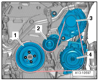
If it is intended to re-install the V-ribbed belt, mark the direction of rotation with chalk or a felt-tip pen before removing it.
  N13-10374
–  Slacken the screw for the guide pulley/V-ribbed belt -arrow- until the V-ribbed belt can be easily removed.
–  Remove the V-ribbed belt.
Install
Installation is performed in the reverse order, pay attention to the following points:
  Note
Before fitting the V-ribbed belt make sure that all assemblies (generator and AC compressor) are securely mounted.
  A13-10796
–  First position the V-ribbed belt on the belt pulleys of the crankshaft and AC compressor and last on the belt pulley of the generator.
1 - Crankshaft-belt pulley
2 - Guide pulley
3 - AC generator
4 - AC compressor
–  Coat the guide surfaces for the guide pulley with the grease G 052 751 A1.
–  Guide the guide pulley with the bolt into the guide in the bracket for auxiliary units.
  A13-10597
–  Screw in the screw for the guide pulley -arrow- until the bolt of the guide pulley is located at the stop (this tensions the V-ribbed belt).
–  Subsequently slacken the screw -arrow- again by 1/4 turn, tighten again to 30 Nm + torque a further 90° (1/4 turn).
  A13-10796
–  Check whether the end of the screw for the guide pulley/V-ribbed belt protrudes beyond the contact surface of the guide pulley. Dimension -a- = approx. 2.5 mm.
–  Check correct positioning of the V-ribbed belt.
–  Start engine and check ribbed V-belt run.
  N13-10346

Removing and installing V-ribbed belt for vehicles with air conditioning system and tensioning element > < Removing and installing V-ribbed belt for vehicles without air conditioning system