skoda Workshop Repair Guides

Skoda Workshop Service and Repair Manuals

Removing and installing camshaft housing > < Removing and installing timing chain and drive chain for cylinder head version A
Removing and installing timing chain and drive chain of the oil pump for cylinder head version B
For engine with identification characters CFNA
Special tools and workshop equipment required
t  Counterholder -T30004 (3415)-
t  Extractor -T10094A-
t  Adapter for dial gauge -T10170-
t  Fixing bolt -T10414-, 2 pieces
t  Counterholder -T10172-
t  Rig pin -T40011-
t  Dial gauge
Removing
   
–  Remove caps -arrows- for camshafts.
–  Remove ignition coil from cylinder 1 → Chapter and release the spark plug.
  N15-10663
–  Screw adapter for dial gauge -T10170- up to the stop into the spark plug thread.
–  Insert the dial gauge -A- with extension -T10170/1- up to the stop and fix in place using the clamping screw -arrow-.
–  Rotate the crankshaft in direction of rotation of engine on TDC for cylinder 1. Note down the position of the small pointer of the dial gauge.
  S15-0279
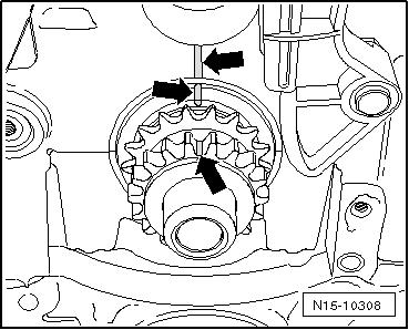
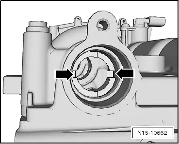
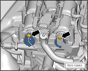
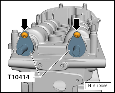
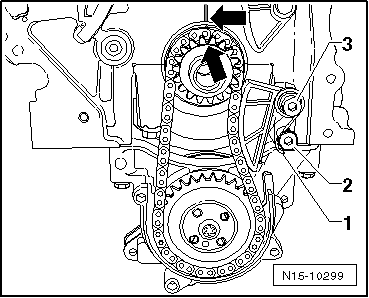
The holes -arrows- in the camshafts must be positioned as shown, if necessary rotate the crankshaft a further revolution (360°).
  Note
t  
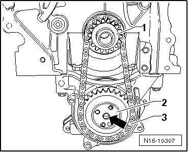
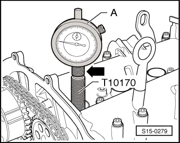
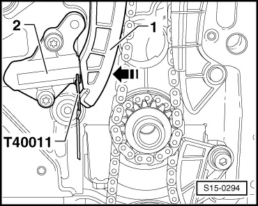
If the crankshaft was turned more than 0.01 mm past the top dead centre, the crankshaft must once again be turned approx 45° in the opposite direction of rotation of the engine. Then position crankshaft in direction of rotation of engine on TDC for cylinder 1.
t  Permissible deviation from TDC for cylinder 1: ± 0.01 mm.
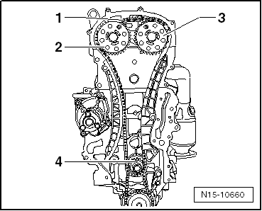
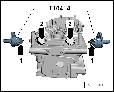
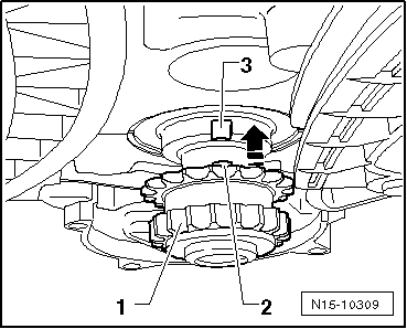
–  Insert the fixing bolt -T10414- up to the stop into the camshaft openings.
  N15-10662
The interlocking lugs -arrow 1- must engage in the holes -arrow 2- of the camshafts.
  N15-10665
–  To secure the fixing bolts -T10414-, screw in the fixing screws -arrows- for the caps of the camshafts by hand, do not tighten forcefully.
–  Remove timing case → Chapter.
  N15-10666
–  Pull off cover -1- from chain sprocket of oil pump.
  N15-10302
–  Press the tensioning rail by hand in the -direction of the arrow- and interlock the piston with the rig pin -T40011-.
–  Remove chain tensioner -2-.
  S15-0294
–  Mark with a suitable felt-tip pen the direction of rotation of the timing chain -3-.
–  Release screws -2- and remove chain sprocket of inlet camshaft -1- with timing chain -3-. Use counterholder -T10172- to counterhold.
  S15-0541
–  Hold chain sprocket of oil pump with counterholder -T10172- and slacken fixing screw -1-.
  N15-10300
–  Lever out tensioning spring -1- at the screw -2- with a screwdriver and remove tensioning spring -1-.
–  Unscrew fixing screw -3- and remove the chain tensioner.
  N15-10299
–  Mark with a suitable felt-tip pen the direction of rotation of the drive chain for oil pump -2-.
–  Unscrew the fixing screw of the chain sprocket -1- and remove the chain sprockets -1- and -3- together with the drive chain for oil pump -2-.
Install
l  The crankshaft must be positioned on TDC for cylinder 1.
  N15-10298
–  Push chain sprocket -1- in -direction of arrow- up to the stop onto the crankshaft journal.
  Caution
The integrated peg -2- of the chain sprocket -1- must fit into the slot -3- at the crankshaft stub.
  N15-10309
–  Mark the positions of the chain sprocket and the crankshaft to the cylinder block with a felt-tip pen.
  N15-10308
–  Fit the drive chain for oil pump -3- onto the chain sprocket -1-.
–  Place the chain sprocket of the oil pump -2- into the drive chain for oil pump -3- and position onto the drive shaft of the oil pump.
  Note
t  Observe the marking of the running direction on the drive chain for oil pump.
t  The chain sprocket of the oil pump only adapts to one postion on the drive shaft of the oil pump -arrow-.
  N15-10307
–  Hold the chain sprocket of the oil pump with the counterholder -T10172-.
–  Tighten the new fixing screw -1- to 20 Nm + torque a further 90° (1/4 turn).
  N15-10300
–  Position the chain sprocket onto the drive chain for the oil pump and tighten the fixing screw -3- to 15 Nm.
–  Lever the tensioning spring -1- onto the screw -2- with a screwdriver.
  Note
t  Observe the markings -arrows-.
t  The crankshaft should not turn.
  N15-10299
–  Screw on the chain sprocket -3- by hand with a new fixing screw.
–  Place the timing chain -1- onto the chain sprocket of the crankshaft -4-, the chain sprocket of the outlet camshaft -3- and screw on the chain sprocket of the inlet camshaft -2- with a new fixing screw.
  Note
Observe the marking of the running direction on the timing chain -1-.
  N15-10660
The timing chain must rest on the sliding rail -1- and on the chain sprocket of the crankshaft -arrow-.
  N15-10305
–  Install the chain tensioner -1- and tighten the fixing screws -2- to 9 Nm.
–  Tighten the timing chain, by pulling out the rig pin -T40011- from the chain tensioner.
–  Check markings on the chain sprocket of the crankshaft and on the cylinder block; they must be positioned opposite to each other.
  N15-10304
–  Tighten fixing screws -2- to 50 Nm (use counterholder -T10172-).
  Note
First the fixing screws -2- are tightened to the torquing angle 90° (1/4 turn), after which the timing is checked.
  S15-0541
–  Unscrew the securing screws -arrows- and remove both fixing bolts -T10414-.
–  Test timing → Chapter.
If timing is o.k.:
  N15-10666
–  Hold the camshaft sprockets with the counterholder -T10172- and torque the fixing screws -2- a further 90° (1/4 turn) with a rigid wrench.
  Note
The camshaft chain sprockets must not turn when tightening.
  S15-0541
–  Install cover for oil pump gear -1-.
–  Install timing case → Chapter.
The further assembly is carried out in reverse order to disassembly.
  N15-10302

Removing and installing camshaft housing > < Removing and installing timing chain and drive chain for cylinder head version A