
Fabia Mk2
|

| 1 - | 40 Nm + torque a further 90° (1/4 turn) |
| q | Left-hand thread |
| q | replace |
| 2 - | 50 Nm + torque a further 90° (1/4 turn) |
| 3 - | Camshaft adjuster |
| q | for inlet valves |
| q | with chain sprocket |
| q | Observe the fitting position of the timing chain |
| q | must not be disassembled |
| q | removing and installing → Chapter |
| 4 - | Sprocket |
| q | for exhaust camshaft |
| q | Observe the fitting position of the timing chain |
| 5 - | Camshaft adjustment valve 1 -N205- |
| 6 - | 10 Nm |
| 7 - | O-ring |
| q | replace |
| q | oil before the assembly |
| 8 - | 10 Nm + torque a further 90° (1/4 turn) |
| q | replace |
| q | tighten from inside to outside |
| 9 - | Camshaft housing |
| q | removing and installing → Chapter |
| 10 - | Roller rocker arm |
| q | inspect roller bearings of roller for smooth operation |
| q | oil contact surfaces |
| q | for installing, clip onto the supporting element and secure with locking clip |
| 11 - | Valve collets |
| 12 - | Supporting element |
| q | do not interchange |
| q | with hydraulic valve clearance compensation |
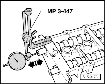
| q | before installing check axial play of the camshaft → Fig. |
| q | oil contact surfaces |
| 13 - | Valve spring retainer |
| 14 - | Valve spring |
| q | removing and installing → Chapter |
| 15 - | Valve stem seal |
| q | replace → Chapter |
| 16 - | Valve guide |
| q | not to be replaced |
| q | check → Chapter |
| 17 - | Cylinder head |
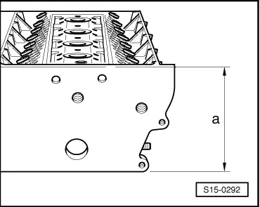
| q | reworking valve seats → Chapter |
| q | reworking sealing surface → Fig. |
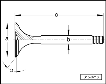
| 18 - | Valves |
| q | do not rework, only grinding in with grinding paste is permissible |
| q | Valve dimensions → Fig. |
| 19 - | Support |
| 20 - | Screw cap |
| q | for hole of inlet camshaft |
| 21 - | Screw cap |
| q | for hole of exhaust camshaft |
| 22 - | Exhaust camshaft |
| q | do not mix up with inlet camshaft |
| q | Inspecting axial play → Fig. |
| q | moisten with oil before installing (also axial bearing collar) |
| 23 - | Inlet camshaft |
| q | do not mix up with exhaust camshaft |
| q | Inspecting axial play → Fig. |
| q | moisten with oil before installing (also axial bearing collar) |
| 24 - | Guide bushing |
 Note
Note
|
|
Note
|
|
| Dimension | Inlet valve | Exhaust valve | |
| Ø a | mm | 29,5 | 26,0 |
| Ø b | mm | 5,973 | 5,953 |
| c | mm | 100,9 | 100,5 |
| α | ∠° | 45 | 45 |