skoda Workshop Repair Guides

Skoda Workshop Service and Repair Manuals

Assembly bracket > < Securing the engine to the assembly stand
Installing the engine
Special tools and workshop equipment required
t  Double ladder, e. g. -VAS 5085-
t  Catch pan, e.g. -VAS 6208-
t  Pliers for spring strap clamps
t  Grease -G 000 100-
t  Cable strap
Precondition
l  Fit engine and gearbox using engine mount -T10416- to the engine/gearbox jack -V.A.G 1383 A-.
Work procedure
Installation is carried out in the reverse order. Pay attention to the following:
  Caution
When undertaking all assembly work, particularly in the engine compartment due to its cramped construction, please observe the following:
t  Lay lines of all kinds (e.g. for fuel, hydraulic fluid, the active charcoal container-unit, cooling fluid and refrigerant, brake fluid, vacuum) and electrical lines in such a way that the original line guide is re-established.
t  In order to avoid damage to the cables, ensure that there is adequate free access to all moving or hot components.
  Note
t  All cable straps should be fastened again in the same place when installing.
t  Secure all hose connections with hose clamps → Electronic Catalogue of Original Parts.
t  Replace the self-locking nuts and screws when undertaking assembly work.
t  Replace screws which have been tightened to a torquing angle as well as gasket rings and seals.
Observe all safety measures and notes for assembly work on the fuel system, on the injection and ignition system and the charge air system as well as rules for cleanliness → Chapter.
For vehicles with manual gearbox
–  Clean the serration of the drive shaft and if the clutch disc has been used clean the hub serration, remove corrosion and only apply a very thin layer of grease -G 000 100- to the serration of the drive shaft. Subsequently move the clutch disc up and down on the drive shaft until the hub fits smoothly on the shaft. Always remove excess grease.
–  After installing the coupling, check the centering of the clutch disc → Gearbox; Rep. gr.30.
–  Check the clutch release bearing for wear. Replace release bearing if worn → Gearbox; Rep. gr.30.
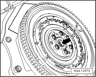
For models with automatic gearbox
   
–  Replace the needle bearing -arrow- in the crankshaft → Chapter.
–  Attach the selector lever control cable at the gearbox → Gearbox; Rep. gr.34.
Continued for all vehicles
–  Check whether the dowel sleeves for centering the engine/gearbox are present in the cylinder block; insert if necessary.
  N34-10979
–  Ensure that the intermediate plate has been inserted on the sealing flange and is pushed onto the dowel sleeves -arrows-.
–  Screw on gearbox to engine → Gearbox; Rep. gr.34.
–  When installing the engine/gearbox assembly, ensure clearance to the assembly carrier, AC compressor as well as to the radiator fans.
–  Tighten the new screws by hand for attaching the engine/gearbox assembly at the engine and gearbox mounts.
For the vehicles Fabia II, Roomster
–  Adjust assembly bracket and tighten screws → Chapter.
–  Install pendulum support → Chapter.
For the vehicles Octavia II, Yeti
–  Adjust assembly bracket → Chapter and tighten screws → Chapter.
–  Install pendulum support → Chapter.
Continued for all vehicles
–  Install drive shafts → Chassis; Rep. gr.40.
For vehicles with air conditioning
–  Install AC compressor → Chapter.
–  Install the V-ribbed belt → Chapter.
Continued for all vehicles
–  Install slave cylinder → Gearbox; Rep. gr.30.
–  Attach shift mechanism and adjust if necessary → Gearbox; Rep. gr.34.
–  Install the engine wiring harness and connect to the engine control unit → Chapter.
For the vehicles Fabia II, Roomster
–  Install catalytic converter with exhaust pipe → Chapter.
For the vehicles Octavia II, Yeti
–  Install exhaust system → Chapter.
Continued for all vehicles
–  Install the battery and pay attention to the necessary work after re-connecting the battery → Electrical System; Rep. gr.27.
–  Checking the oil level:
t  → BookletFabia II.
t  → BookletRoomster.
t  → BookletOctavia II.
t  → BookletYeti.
–  Top up and bleed cooling system → Chapter.
–  Interrogate all fault memories and delete all fault entries, which are caused by removing and installing the engine → Vehicle diagnostic tester.
   After deleting the fault memory of the engine control unit the readiness code must be re-generated.
–  Perform a test drive.
–  Then perform a vehicle system test and if necessary eliminate the resulting faults.
Tightening torques
  S13-0541
Component Nm 
Screws and nutsM610 
 M713
 M820
 M1045
 M1260
deviations: 
Engine/gearbox connecting screws → Gearbox; Rep. gr.34
Screws for assembly bracket:
t  Fabia II, Roomster → Chapter
t  Octavia II, Yeti → Chapter


Assembly bracket > < Securing the engine to the assembly stand