skoda Workshop Repair Guides

Skoda Workshop Service and Repair Manuals

Securing the engine to the assembly stand > < Removing and installing engine
Removing
Removing
  Note
t  
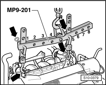
The engine is removed towards the front together with the gearbox.
t  All cable straps that have been loosened or cut open when the engine was removed must be attached again in the same location when the engine is installed again.
t  Collect drained coolant in a clean container for reuse or proper disposal.
–  Observe all safety measures and notes for assembly work on the fuel supply, injection and ignition system; as well as the rules for cleanliness → Chapter.
  WARNING
Observe measures when disconnecting the battery → Electrical System → Rep. gr.27.
–  Remove battery and battery tray → Electrical System → Rep. gr.27.
–  Remove air filter housing with air guide → Chapter.
–  Remove bottom noise insulation → Body Work → Rep. gr.50.
–  Remove the front wheelhouse liners → Body Work → Rep. gr.66.
–  Remove front bumper → Body Work → Rep. gr.63.
–  Drain coolant → Chapter.
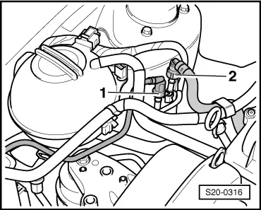
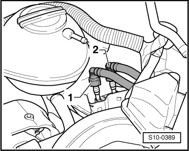
–  Separate coolant hoses from radiator and from heat exchanger.
–  Disconnect plugs from radiator fan -V7- and from thermoswitch for radiator fan -F18-.
–  Disconnect plug of front headlights, turn signal lights, horn, sensor for exterior temperature indicator and switch for engine bonnet lock.
–  Remove lock carrier with headlights and radiator if necessary also with AC condenser → Body Work → Rep. gr.50.
Vehicles with air conditioning
  Note
Carefully swivel the lock carrier with installed AC condenser to the side and position on a suitable base. Do not separate refrigerant lines.
For vehicles with engine identification characters BUD, BXW
   
–  Disconnect the fuel feed line -2- and the vent line -1-.
For vehicles with engine identification characters CGGB
  S20-0316
–  Disconnect the fuel feed line -2- and the vent line -1-.
Continued for all vehicles
   To do so press in the securing rings.
–  Seal the lines in order to prevent any dirt from penetrating into the fuel system.
–  Disconnect the vacuum and bleeder hoses from the engine or from other components.
–  Remove/unclamp all electrical lines from the engine, generator, starter and gearbox and uncover them.
–  Remove pre-exhaust pipe with catalytic converter → Chapter.
  S10-0389
–  Unscrew the pendulum support -arrows-.
–  Remove shift mechanism from gearbox → gearbox → Rep. gr.34.
–  Remove slave cylinder → Gearbox → Rep. gr.30.
  Note
Do not depress the clutch pedal.
Vehicles with air conditioning
–  Remove V-ribbed belt → Chapter.
–  Remove AC compressor from holder → Heating, Air Conditioning → Rep. gr.87.
–  Secure the air-conditioning compressor with attached lines to the assembly carrier.
Continued for all vehicles
–  Unscrew drive shaft to the right and left of the gearbox and tie up → Chassis → Rep. gr.40.
  S34-0337
–  Hang lifting device -MP9-201 (2024 A)- as follows and slightly raise engine with the workshop crane.
Belt pulley side: 2nd hole of the extension in Position 1.
Flywheel side: 1st hole of the extension in Position 5.
  WARNING
Use securing pins on the hooks and rig pins -arrows-.
For vehicles Roomster with engine identification characters BUD, BXW
–  Disconnect bleeder hose and activated charcoal filter from holder.
For all vehicles
–  Unscrew the coolant expansion bottle and and lay to one side (the hoses remain connected).
  S10-0379
–  Unscrew screws -arrows- and remove engine mount.
  S10-0380
–  Unscrew screws -arrows- and remove gearbox mount.
–  Raise the engine with gearbox and carefully pull out towards the front.
  Note
Engine with gearbox must be guided carefully when pulling out, in order to avoid damaging the body.
  S10-0381

Securing the engine to the assembly stand > < Removing and installing engine