skoda Workshop Repair Guides

Skoda Workshop Service and Repair Manuals

Inspecting semi-automatic tensioning pulley > < Removing
Install
Install
Conditions
l  The pistons must not be positioned at top dead centre.
l  The crankshaft - toothed belt sprocket is secured to the crankshaft with fixing screw and two washers.
l  Lock the camshaft sprockets with camshaft lock -T10016- in the fit holes of the cylinder head cover and secure against turning.
  Note
When turning the camshaft the valves may touch the piston in TDC.
Work procedure
   
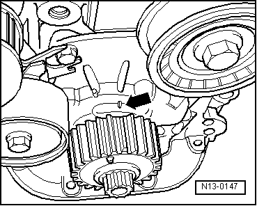
–  Position crankshaft on TDC for cylinder 1. The chamfered tooth must correspond with the marking on the sealing flange -arrow-.
–  Fit on coupling drive - toothed belt. If the toothed belt has been used pay attention to the rotation direction.
Install the coupling drive tensioning pulley as follows:
  N13-0147
–  Turn the coupling drive tensioning pulley with Allan screw -1- clockwise in the direction of the marking window -arrow-, (tensioning pulley in released position).
–  Push the bottom part of the coupling drive-toothed belt upwards using the tensioning pulley and screw in the fixing screw of the tensioning pulley.
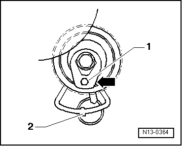
–  Tighten fixing screw manually. The peg of the base plate -2- must engage in the bore in the cylinder head.
  N13-0364
–  Subsequently tension the toothed belt by turning the tensioning pulley anti-clockwise until the pointer -2- is positioned above the peg -arrow- of the base plate in the marking window.
–  Tighten the fixing screw on the tensioning pulley. Tightening torque: 20 Nm
–  Remove camshaft lock -T10016-.
–  Turn the crankshaft or toothed belt gear from TDC half a tooth anti-clockwise (approx 1.5 mm).
–  Fit on main drive toothed belt.
–  Fix the two camshaft sprockets with camshaft lock -T10016-.
If the tensioning pulley has been removed beforehand, install tensioning pulley as follows:
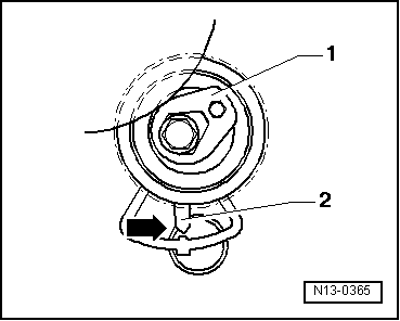
  N13-0365
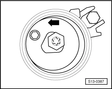
–  Turn tensioning pulley with Allan key anti-clockwise in the marked position -arrow-.
  S13-0387
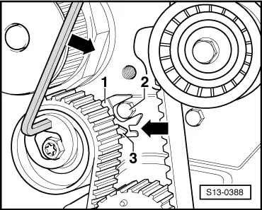
–  Tighten fixing screw manually. The screw in the cylinder block -2- must lock in the recess on the base plate -1-.
–  Subsequently tension the toothed belt in the direction of the arrow by turning the tensioning pulley until the pointer -3- is positioned above the notch -arrow- in the base plate.
–  Tighten the fixing screw on the tensioning pulley. Tightening torque: 20 Nm
–  Remove camshaft lock -T10016-.
  S13-0388
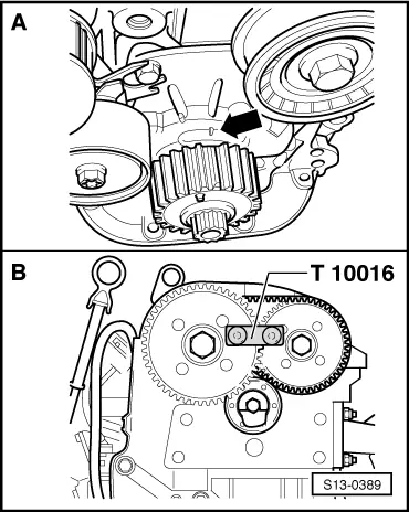
–  Now rotate crankshaft 2 revolutions in direction of rotation of engine until it is again positioned on TDC for cylinder 1. The chamfered tooth must correspond with the marking on the sealing flange -arrow- in the fig. -A-.
In this position both camshaft sprockets must lock with camshaft lock -T10016- fig. -B-.
–  Then inspect the toothed belt setting and tensioning pulley setting again, if necessary repeat tensioning of the two toothed belts.
–  Install bottom timing belt guard.
–  Install crankshaft belt pulley. Pay attention to the following:
t  The fixing screws for the belt pulley and toothed belt gear must be replaced.
t  Pay attention to the toothed belt gear attachment when installing the belt pulley.
t  The clamping surfaces of the belt pulley and the screw must be degreased.
t  Tightening process for the new oiled screw: 150 Nm + torque a further 1/2 turn (180°).
t  Counterhold crankshaft belt pulley with counterholder -T30004 (3415)- and replaceable bolt -T30004/1 (3415/1)-.
–  Attach engine mount to cylinder head. Tightening torque 50 Nm
–  Install engine assembly bracket. Tightening torques → Chapter.
–  Install top toothed belt guard.
–  Install the V-ribbed belt → Chapter.
  Note
Pay attention to the correct position of the V-ribbed belt in the belt pulley when installing it.
–  Install the front right wheelhouse liner → Body Work → Rep. gr.66.
–  Install the noise insulation.
–  Screw on the coolant expansion reservoir.
–  Connect hose for crankcase ventilation and install engine cover with air filter → Chapter.
  S13-0389

Inspecting semi-automatic tensioning pulley > < Removing