skoda Workshop Repair Guides

Skoda Workshop Service and Repair Manuals

Checking/removing and installing parts of the ABS system on the rear axle (disc brake and drum brake) - front-wheel drive > < Repairing the hydraulic control unit
Checking/removing and installing parts of the ABS system on the front axle
Special tools and workshop equipment required
t  Wiring loom repair kit, e.g. Skoda Car Tool Kit Škoda, Order No.: S 504 500 V
t  Solid lubricant paste-G 000 650-
Removing and installing wheel speed sensor
Removing
–  Raise vehicle.
   
–  Separate plug connection of wheel speed sensor/wheel speed sensor cable -arrow-.
–  Release screw -2-.
–  Take the wheel speed sensor -G45- / -G47- out of the wheel bearing housing.
Install
–  Clean the inner surface of the hole before inserting the wheel speed sensor and coat with a solid lubricant paste -G 000 650-.
–  Insert the wheel speed sensor in the bore of the wheel-bearing housing and tighten the screw to 8 Nm.
–  Fit together the plug connection of wheel speed sensor cable/wheel speed sensor.
–  Actuate steering from left to right up to the stop and check for free movement of the wheel speed sensor cable.
–  Lower the vehicle.
Check pulse rotor or remove and install
–  Raise vehicle.
–  Remove wheel.
  A01-0010
–  While turning the brake disc, check the pulse rotor -1- for any dirt or damage.
–  If the chunking of the pulse rotor is blocked by dirt, the pulse rotor must be cleaned.
–  If the pulse rotor is damaged, the wheel hub together with the pulse rotor must be replaced → Axles, steering; Rep. gr.40.
–  Attach the wheel.
–  Lower the vehicle.
Check axial run-out of pulse rotor
–  Raise vehicle.
–  Remove wheel.
  A01-0010
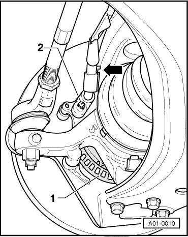
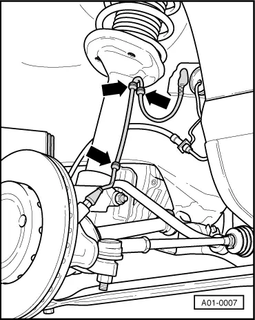
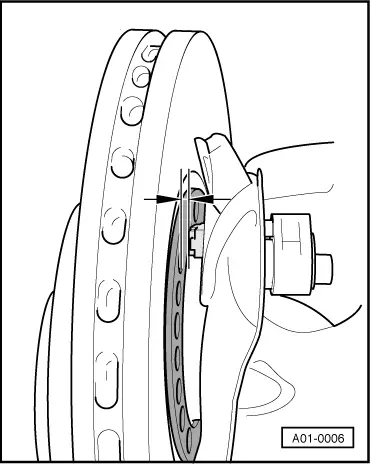
–  Turn the wheel hub and check the distance between the pulse rotor and the wheel speed sensor for evenness (axial run-out tolerance). In this test, the wheel bearing play must be accounted for.
l  The axial run-out tolerance of the pulse rotor is 0.3 mm.
–  If the axial run-out tolerance is not kept, change the pulse rotor together with the wheel hub → Axles, steering; Rep. gr.40.
–  Attach the wheel.
–  Lower the vehicle.
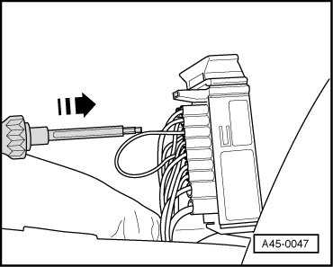
Removing and installing the wheel speed sensor cables
Removing
  Note
t  It is prohibited to repair shielded leads of the ABS system.
t  Before disconnecting the battery determine the code of radio sets fitted with anti-theft coding.
t  After connecting the battery, perform the following:
–  on vehicles with radio encoding, carry out the coding,
–  re-set clock,
–  initialise power windows on vehicles fitted with power windows → BookletOctavia
–  Disconnect battery.
  Note
The following 2 work steps do not apply to the 1.6 ltr./55 kW engine:
  A01-0006
–  Disconnect the plug of the air mass meter -1- from the air guide pipe of the air filter.
–  Unscrew screws -2- at the air filter -3- and lay it aside.
–  Remove the relay carrier above the brake servo unit on diesel engines.
  A45-0041
–  Release the multi-pin connector and remove it from the ABS control unit.
  S45-0287
–  Slacken the cap of the multi-pin connector using a screwdriver and remove it.
  A45-0045
–  Release secondary lock (purple) with a small screwdriver in the -direction of the arrow-.
  A45-0046
Contact assignment of the plug connection wiring loom/ABS control unit -J104-
  N45-0037
ContactWiring to component ...
19 + 20Front right wheel speed sensor -G45-
1 +2Front left wheel speed sensor -G47-
22 + 23Rear right wheel speed sensor -G44-
5 + 6Rear left wheel speed sensor -G46-

   
–  Press out the relevant contacts using a suitable ejection tool from the wiring loom repair kit.
–  Release plug connection on wheel speed sensor and separate plug connector.
–  Remove defective wheel speed sensor cable.
Install
–  Draw in new wheel speed sensor cable.
–  Connect wheel speed sensor cable to wheel speed sensor.
  S45-0290
–  Clip in wheel speed sensor cable -arrows-.
  Note
When assembling the wheel speed sensor cable make sure it is not twisted when installed in the wheelhouse.
  A01-0007
–  Insert contact in the plug housing and insert the single cable seal with a suitable plug-in tool from the wiring loom repair kit up to the stop.
–  Secure the contacts with the secondary lock and position the cap of the multi-pin connector.
–  Connect battery → Electrical System; Rep. gr.27.
–  Interrogate the fault memory → Chapter.
–  Erasing fault memory → Chapter.
  A45-0047

Checking/removing and installing parts of the ABS system on the rear axle (disc brake and drum brake) - front-wheel drive > < Repairing the hydraulic control unit