
Octavia Mk1
 Note
Note
|

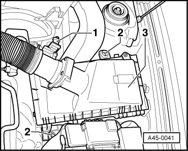
| 1 - | Hydraulic control unit |
| t | the hydraulic pump -V64-, the hydraulic unit -N55- and the ABS control unit -J104- form the hydraulic control unit. |
| t | the hydraulic control unit must be removed and installed as a whole unit |
| t | repairing → Chapter |
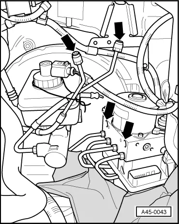
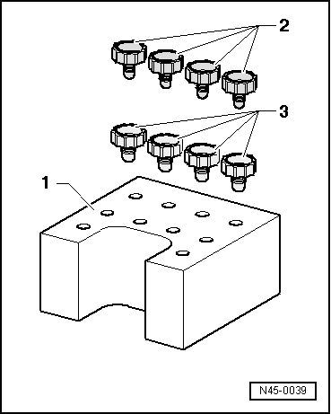
| 2 - | Brake line, 14 Nm |
| t | between the master brake cylinder/floating piston circuit and ABS hydraulic unit |
| 3 - | Brake line, 14 Nm |
| t | ABS hydraulic unit to front left brake caliper |
| 4 - | Brake line, 14 Nm |
| t | ABS hydraulic unit to wheel cylinder/rear right brake caliper |
| 5 - | Brake line, 14 Nm |
| t | ABS hydraulic unit to wheel cylinder/rear left brake caliper |
| 6 - | Brake line, 14 Nm |
| t | ABS hydraulic unit to front right brake caliper |
| 7 - | Brake line, 14 Nm |
| t | between master brake cylinder/push rod piston circuit and hydraulic unit |
| 8 - | Multi-pin connector/ABS control unit |
| t | 25-pin |
| t | do not disconnect the plug connector before the self-diagnosis is complete, switch off the ignition before disconnecting the plug connector |
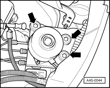
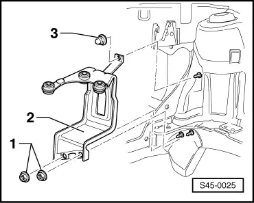
| 9 - | Self-locking nut, 20 Nm |
| 10 - | Support |
| 11 - | Dowel screw, 8 Nm |
| 12 - | Cap nut, 25 Nm |
Note
Note
|
|
|
|
|
Note
|
|
Note
|
|
|
|
Note
Note
|
|
|
|
|
|