skoda Workshop Repair Guides

Skoda Workshop Service and Repair Manuals

Removing and installing the brake servo unit - RHD vehicles > < Check brake servo unit
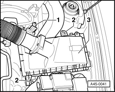
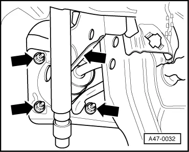
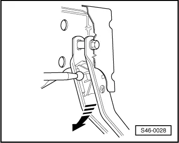
Removing and installing the brake servo unit - LHD vehicles
Special tools and workshop equipment required
t  Hose clamp -MP 7-602-
t  Brake pedal load, e.g. -V.A.G 1238 B- or -V.A.G 1869/2-
t  Vehicle system tester -V.A.G 1552-
t  Diagnostic cable -V.A.G 1551/3, 3A, 3B oder 3C-
t  Release tool -T 10159 A-
t  Extraction bottle (commercially available)
t  Repair kit -1 HO 698 311 A-
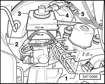
t  Brake fluid → Chapter
  Note
t  Before disconnecting the battery determine the code of the radio sets fitted with anti-theft coding.
t  After connecting the battery check the vehicle equipment:
–  on vehicles with radio encoding, carry out the coding,
–  set clock,
–  initialise power windows on vehicles fitted with power windows → BookletOctavia
Removing
–  Disconnect battery.
   
–  Disconnect the plug -1- of the air mass meter from the air guide pipe of the air filter.
–  Unscrew screws -2- at the air filter -3- and lay it aside.
–  Remove the relay carrier above the brake servo unit on diesel engines.
–  Lay sufficient non-fluffing cloths around the plenum chamber, the engine and the gearbox.
–  Remove hydraulic control unit -1- → Chapter.
  A45-0041
–  Disconnect plug -4- from brake fluid level warning contact -F34-.
–  Clamp off the running-on line of the clutch master cylinder -5- with hose clamp -MP 7-602-.
–  Disconnect the running-on line of the clutch master cylinder -5- from the brake fluid reservoir -3- and tie up.
–  Detach the vacuum hose -2- from the brake servo unit.
  S47-0066
–  Press the plug connection -1- out of the holder -3-.
To do so, press the plug connection -1- in the direction of the bulkhead.
2 - Brake servo unit
–  Disconnect plug connection -1-.
  S47-0067
–  Release screws -2-.
–  Pull the footwell covering -1- out of the holders.
–  Separating the brake pedal from the brake servo unit → Chapter.
  S47-0061
–  Unscrew the nuts for brake servo unit -arrows-.
The top right nut is not visible in the figure.
–  Guide the brake servo unit with master brake cylinder towards the front and remove.
Install
  A47-0032
–  Install the brake servo unit with the master brake cylinder and tighten the new nuts -arrows-.
  A47-0032
–  Clip the brake pedal onto the brake servo unit → Chapter.
–  Installing and setting brake light switch vehicles up to MY 1999 → Chapter, vehicles as of MY 2000 → Chapter.
Further installation occurs in reverse order.
–  Fill up with new brake fluid → Chapter.
–  Connect battery → Electrical System; Rep. gr.27.
–  Bleeding Brake System → Chapter.
–  Bleed clutch system (manual gearbox) → Manual Gearbox; Rep. gr.30.
–  Initiate basic setting → Chapter.
–  Interrogate the fault memory → Chapter.
–  Erasing fault memory → Chapter.
  S46-0028
Tightening torque:
Brake servo unit to foot controls28 Nm


Removing and installing the brake servo unit - RHD vehicles > < Check brake servo unit