
Octavia Mk1
 Note
Note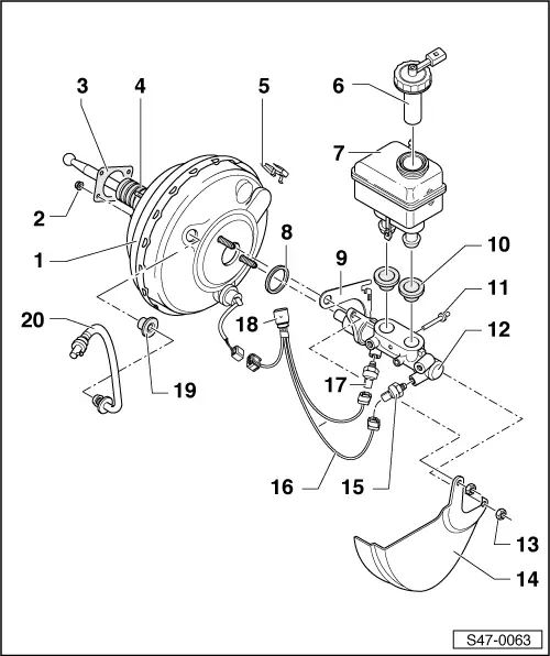
| 1 - | Brake servo unit |
| t | check → Chapter |
| t | removing and installing - LHD vehicles → Chapter |
| t | removing and installing - RHD vehicles → Chapter |
| t | if there are faults replace completely |
| t | separate from brake pedal → Chapter |
| t | Assignment → Electronic Catalogue of Original Parts |
| t | on petrol engines the required negative pressure is drawn from the induction pipe |
| t | vehicles using a diesel engine are fitted with a vacuum pump for generating a low pressure |
| t | Non-return valve (in the vacuum hose of the vacuum pump) |
| Functional test |
| – | It must be possible to blow through the valve in the -direction of the arrow-. |
| – | Against the direction of the arrow the valve must be closed. |
| 2 - | Self-locking nut 28 Nm |
| t | replace |
| 3 - | Gasket |
| t | for brake servo unit |
| t | between brake servo unit and bulkhead |
| 4 - | Bellows |
| t | pay attention to correct position, risk of suction noises |
| 5 - | Holder |
| t | is attached to the edge of the brake servo unit |
| t | serves for the support of the plug -Pos. 18- |
| 6 - | Screw cap |
| t | with integrated brake fluid level warning contact -F34- |
| 7 - | Brake fluid reservoir |
| t | locked with lateral catches in the retaining pin |
| 8 - | Sealing ring |
| t | replace |
| 9 - | Retaining bracket |
| t | for fixing the wiring loom -Pos. 16- |
| 10 - | Plugs |
| t | moisten with brake fluid and press in expansion reservoir |
| 11 - | Retaining pin |
| t | fit through the master brake cylinder |
| 12 - | Master brake cylinder |
| t | cannot be repaired, replace completely in the event of faults |
| t | Check tightness → Chapter |
| 13 - | Self-locking nut 20 Nm |
| t | replace |
| 14 - | Heat shield |
| t | only for vehicles with 74 kW, 92 kW and 110 kW engine |
| 15 - | Brake pressure sender -1--G201- |
| t | in the floating piston circuit |
| t | removing and installing → Chapter |
| 16 - | Wiring loom |
| 17 - | Brake pressure sender -2--G214- |
| t | in the push rod piston circuit |
| t | removing and installing → Chapter |
| 18 - | Connector |
| t | Connection wiring loom dash panel/engine compartment |
| 19 - | Plugs |
| 20 - | Vacuum hose |
| t | with non-return valve |
| t | insert in brake servo unit. |