
Octavia Mk1
 Note
Note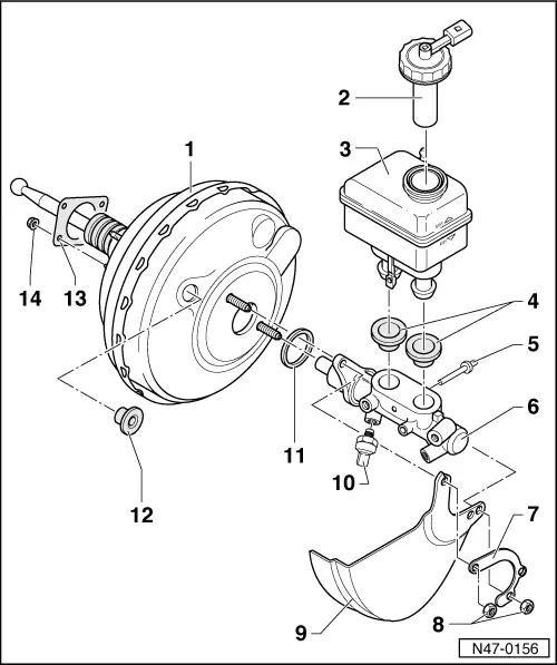
| 1 - | Brake servo unit without mechanical brake assistance |
| t | Right-hand drive vehicles with ABS/EDL/TCS/ESP Mark 60 |
| t | Left-hand drive vehicles with ABS/EDL/TCS/ESP Mark 60 up to and including model year 2001 |
| - Brake servo unit with mechanical brake assistance |
| t | Left-hand drive vehicles with ABS/EDL/TCS/ESP Mark 60 as of model year 2002 |
| t | The brake assistance can only be recognized by the spare part number of the brake servo unit |
| t | The brake assistance cannot be repaired, replace the brake servo unit completely when handling a fault LHD vehicles → Chapter, RHD vehicles → Chapter |
| - Continued for all brake servo units |
| t | check → Chapter |
| t | removing and installing LHD vehicles → Chapter, RHD vehicles → Chapter |
| t | if there are faults replace completely |
| t | separate from brake pedal → Chapter |
| t | on petrol engines the required negative pressure is drawn from the induction pipe |
| t | vehicles using a diesel engine are fitted with a vacuum pump for generating a low pressure |
| t | the electric brake vacuum pump is additionally installed on vehicles with automatic gearbox and in combination with EU4 -V192- |
| t | -V192- check operation → Chapter |
| t | Remove and install the brake vacuum pump -V192- → Chapter |
| t | Non-return valve (in the vacuum hose of the vacuum pump) |
| Functional test |
| – | It must be possible to blow through the valve in the -direction of the arrow-. |
| – | Against the direction of the arrow the valve must be closed. |
| 2 - | Screw cap |
| t | with integrated brake fluid level warning contact -F34- |
| 3 - | Brake fluid reservoir, left-hand drive |
| t | locked with lateral catches in the retaining pin |
| 4 - | Plugs |
| t | moistened with brake fluid, press in expansion reservoir |
| 5 - | Retaining pin |
| t | fit through the master brake cylinder |
| 6 - | Master brake cylinder |
| t | cannot be repaired, replace completely in the event of faults |
| 7 - | Retaining bracket |
| t | serves to fix the wiring loom |
| 8 - | Self-locking nut 20 Nm |
| t | always replace |
| 9 - | Heat shield |
| t | only for vehicles with 74 kW, 92 kW, 110 kW and 132 kW engine |
| 10 - | Brake pressure sender -1--G201- |
| t | removing and installing → Chapter |
| 11 - | Sealing ring |
| t | always replace |
| 12 - | Plugs |
| t | Connection for vacuum hose |
| t | insert in brake servo unit. |
| 13 - | Gasket |
| t | for brake servo unit |
| t | between brake servo unit and bulkhead |
| t | always replace |
| 14 - | Self-locking nut 20 Nm |