
Octavia Mk1
 Note
Note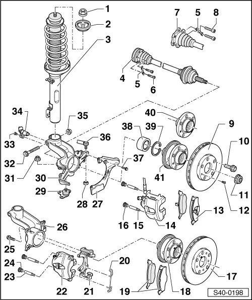
| 1 - | Self-locking nut, 60 Nm |
| t | replace after each removal |
| 2 - | Stop |
| 3 - | Suspension strut |
| t | removing and installing → Chapter |
| t | repairing → Chapter |
| t | Assignment → Electronic Catalogue of Original Parts |
| 4 - | Drive shaft with inner CV joint |
| t | removing and installing → Chapter |
| t | repairing → Chapter |
| 5 - | Shim |
| 6 - | Fillister head screw with internal serrations |
| t | replace after each removal |
| t | initially tighten to 10 Nm and subsequently tighten crosswise to final torque: |
| M8 = 20 Nm + 180° |
| M10 = 50 Nm + 45° |
| t | Assignment → Electronic Catalogue of Original Parts |
| 7 - | Drive shaft with inner tripod joint |
| t | removing and installing → Chapter |
| t | repairing → Chapter |
| 8 - | Fillister head screw with internal serrations |
| t | replace after each removal |
| t | initially tighten to 10 Nm and subsequently tighten crosswise to final torque: |
| M8 = 20 Nm + 90° |
| M10 = 50 Nm + 45° |
| t | Assignment → Electronic Catalogue of Original Parts |
| 9 - | Brake disc (FS-III) |
| t | without marking for axial run-out |
| t | with a fixing hole for the wheel hub |
| t | Assignment → Electronic Catalogue of Original Parts |
| 10 - | Wheel screw, 120 Nm |
| 11 - | Self-locking twelve-point nut |
| t | slacken and tighten → Chapter |
| t | replace after each removal |
| 12 - | 4 Nm |
| 13 - | Brake discs (FS-III) |
| t | removing and installing → Chapter |
| 14 - | Brake caliper (FS-III) |
| Including for vehicles with engine up to 92 kW. |
| t | do not release brake hose when working on the front wheel suspension |
| t | tie up with wire or anything similar |
| t | repairing → Chapter |
| 15 - | Guide bolt (FS-III), 30 Nm |
| t | removing and installing → Chapter |
| 16 - | Cap (FS-III) |
| 17 - | Brake disc (FN 3) |
| t | with marking for maximum axial run-out |
| t | with 5 fixing holes for the wheel hub |
| t | removing and installing → Chapter |
| t | Assignment → Electronic Catalogue of Original Parts |
| 18 - | Wheel hub with pulse rotor for wheel speed sensor |
| t | with marking for minimum axial run-out |
| t | only on vehicles with ABS |
| t | pressing out → Chapter |
| t | installing → Chapter |
| t | Pull off the inner ring of the bearing → Chapter |
| t | Check axial run-out of pulse rotor → Chapter |
| t | Assignment → Electronic Catalogue of Original Parts |
| 19 - | Brake discs (FN-3) |
| t | removing and installing → Chapter |
| 20 - | Retaining spring (FN-3) |
| 21 - | Brake carrier (FN-3) |
| 22 - | Brake caliper (FN-3) |
| Including for vehicles with engine as of 96 kW. |
| t | do not release brake hose when working on the front wheel suspension |
| t | tie up with wire or anything similar |
| t | Removing and installing brake pads → Chapter |
| t | repairing → Chapter |
| 23 - | Guide bolt (FN-3), 30 Nm |
| t | removing and installing → Chapter |
| 24 - | Cap (FN-3) |
| 25 - | Screw with securing collar (FN-3), 124 Nm |
| t | Clean ribbing on the underside |
| 26 - | Wheel-bearing housing |
| Including for vehicles with engine as of 96 kW. |
| t | removing and installing → Chapter |
| t | repairing → Chapter |
| t | before pressing in the wheel bearing, coat the entire wheel bearing seat in the wheel bearing housing evenly with -G 052 723 A2- |
| 27 - | Cover plate |
| 28 - | Self-locking nut, 50 Nm |
| t | replace after each removal |
| 29 - | Steering joint |
| t | check → Chapter |
| t | Inspect rubber bellows for damage, if necessary replace |
| t | removing and installing → Chapter |
| 30 - | Wheel-bearing housing |
| Including for vehicles with engine up to 92 kW. |
| t | removing and installing → Chapter |
| t | repairing → Chapter |
| t | before pressing in the wheel bearing, coat the entire wheel bearing seat in the wheel bearing housing evenly with -G 052 723 A2- |
| 31 - | Self-locking nut, 20 Nm + 90° |
| t | replace after each removal |
| 32 - | Screw |
| t | replace after each removal |
| 33 - | 8 Nm |
| 34 - | ABS wheel speed sensor |
| t | only on vehicles with ABS |
| t | insert with solid lubricant paste -G 000 650- (e.g. Wolfrakote Top Paste) |
| 35 - | Self-locking nut |
| t | up to 05.98: 50 Nm + 90° |
| t | as of 06.98: 60 Nm + 90° |
| t | replace after each removal |
| 36 - | Track rod with track rod end |
| t | removing and installing → Chapter |
| 37 - | 10 Nm |
| 38 - | Wheel bearing |
| t | press out → Chapter |
| t | replace, is damaged when pressing out |
| t | installing → Chapter |
| t | The spare part is only delivered as a set „wheel bearing with mounting parts“ (Pos. 11, 39, 38, 28, 31 and 35) |
| 39 - | Circlip |
| t | pay attention to correct position → Chapter |
| t | replace after each removal |
| 40 - | Wheel hub without pulse rotor |
| t | only on vehicles without ABS |
| t | Assignment → Electronic Catalogue of Original Parts |
| 41 - | Wheel hub with pulse rotor for wheel speed sensor |
| t | without marking for minimum axial run-out |
| t | only on vehicles with ABS |
| t | press out → Chapter |
| t | installing → Chapter |
| t | Pull off the inner ring of the bearing → Chapter |
| t | Check axial run-out of pulse rotor → Chapter |
| t | Assignment → Electronic Catalogue of Original Parts |