
Octavia Mk1
 Note
Note
|
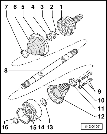
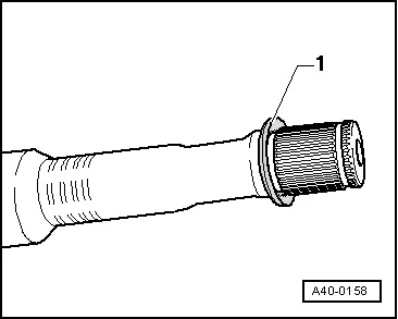
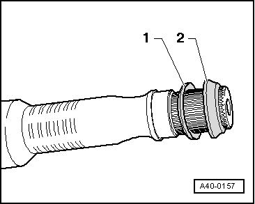
| 1 - | Outer CV joint |
| t | must be replaced completely |
| t | removing → Fig. |
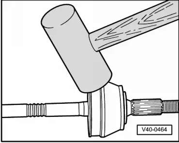
| t | install: drive onto the shaft with a plastic hammer until the compressed circlip expands |
| t | grease → Chapter |
| t | check → Chapter |
| 2 - | Circlip |
| t | replace |
| t | insert into the groove at the shaft |
| 3 - | Thrust ring |
| t | Fitting position → Fig. |
| 4 - | Disc spring |
| t | Fitting position → Fig. |
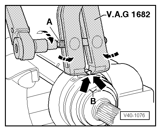
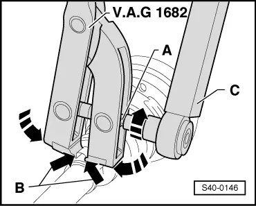
| 5 - | Open warm-type clamp |
| t | replace |
| t | tension with tensioning pliers, e.g. -V.A.G 1682- → Fig. |
| 6 - | Joint boot |
| t | Material: Hytrel (Polyelastomere) |
| t | inspect for tears and chafing points |
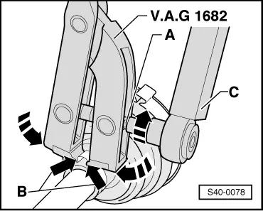
| 7 - | Open warm-type clamp |
| t | replace |
| t | tensioning → Fig. |
| 8 - | Drive shaft (solid shaft) |
| t | Assignment → Electronic Catalogue of Original Parts |
| 9 - | 39 Nm |
| t | M8 x 48 |
| 10 - | Shim |
| 11 - | Open warm-type clamp |
| t | replace |
| t | tensioning → Fig. |
| 12 - | Joint boot for inner CV joint |
| t | Material: Hytrel (Polyelastomere) |
| t | inspect for tears and chafing points |
| t | remove with a drift |
| 13 - | Disc spring |
| t | Fitting position → Fig. |
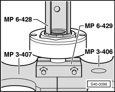
| 14 - | Inner CV joint |
| t | must be replaced completely |
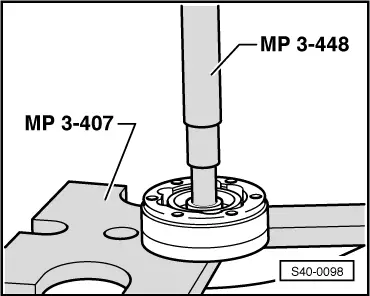
| t | pressing off → Fig. |
| t | pressing on → Fig. |
| t | grease → Anchor |
| t | check → Chapter |
| 15 - | Gasket |
| t | The adherend on the inner CV joint must be free of grease and oil! |
| t | replace |
| t | Remove the protective foil and stick the gasket into the inner joint |
| 16 - | Circlip |
| t | replace |
| t | remove and install with sprung pliers, e.g. -VW161 A- |
Note
|
| Grease | of which in: | ||
| Outer joint | Total amount | Joint | Joint boot |
| Ø mm | [g] | [g] | [g] |
| 90 | 90 | 40 | 40 |
| Inner joint | |||
| 100 | 120 | 50 | 70 |
|
|
Note
|
|
|
|
|
|
|
|
|
|
|
|