
Octavia Mk1

| 1 - | Wheel screw, 120 Nm |
| 2 - | 4 Nm |
| 3 - | Brake disc |
| 4 - | Cap |
| t | replace after each removal |
| t | press off → Chapter, - Pos. 5 |
| t | drive in → Chapter, - Pos. 5 |
| 5 - | Self-locking twelve-point nut 70 Nm +40° |
| t | replace after each removal |
| 6 - | Wheel hub with wheel bearing and pulse rotor |
| t | only on vehicles with ABS |
| t | The wheel bearing and the wheel hub are fitted together in one housing |
| t | this component is maintenance-free and requires no clearance adjustment; adjustment as well as repair work are not possible |
| t | removing and installing → Chapter |
| t | must be replaced completely |
| 7 - | 30 Nm + 90° |
| t | replace after each removal |
| 8 - | Cover plate |
| 9 - | Holder for hand-brake cable |
| t | replace |
| 10 - | Hand-brake cable |
| 11 - | 45 Nm + 90° |
| t | replace after each removal |
| t | when tightening the screw, the axle body must be in the horizontal position (unladen condition) |
| 12 - | Self-locking screw, 30 Nm + 90° |
| t | replace after each removal |
| t | if the thread of the weld nut is damaged, it can be repaired using Heli-Coli threaded insert; while paying attention to the fitting instructions of the manufacturer |
| t | the rework of the thread for the weld nut is permissible on maximum 2 screw points per axle |
| 13 - | Self-locking nut |
| 14 - | Mount for rear axle |
| t | check the overall track of the rear axle after installation and adjust if necessary |
| t | avoid slackening in order to remove the rear axle |
| 15 - | Holder for hand-brake cable |
| 16 - | Rubber-metal bearing |
| t | removing and installing → Chapter |
| 17 - | 20 Nm + 45° |
| t | replace after each removal |
| 18 - | Balancing weight |
| 19 - | ABS wheel speed sensor |
| t | only on vehicles with ABS |
| 20 - | 8 Nm |
| 21 - | Axle body |
| t | The locating face and the threaded holes for axle studs must be free from enamel and dirt |
| 22 - | bottom base |
| 23 - | Coil spring |
| t | removing and installing → Chapter |
| t | check for paint damage, if necessary eliminate paint damage |
| t | Assignment → Electronic Catalogue of Original Parts |
| t | per rear axle only use helical springs of the same make |
| 24 - | top base |
| t | installing → Anchor |
| 25 - | 40 Nm + 90° |
| t | replace after each removal |
| t | insert from the outside of the vehicle |
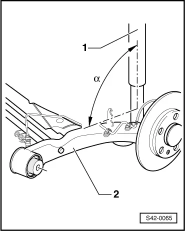
| t | when tightening, take the installation angle of the rear axle to the shock absorber into account → Fig. |
| t | While the vehicle is standing on its wheels, load the luggage compartment with approx. 100 kg and tighten the screw |
| 26 - | Self-locking screw, 30 Nm + 90 |
| t | replace after each removal |
| t | if the thread of the weld nut is damaged, it can be repaired using Heli-Coli threaded insert; while paying attention to the fitting instructions of the manufacturer |
| t | the rework of the thread for the weld nut is permissible on maximum 2 screw points per axle |
| 27 - | Shock absorber |
| t | can be replaced individually |
| t | removing and installing → Chapter |
| t | Assignment → Electronic Catalogue of Original Parts |
| t | disposing of → Chapter |
| t | Inspecting the shock absorber → Chapter |
| t | per rear axle only use shock absorbers of the same make |
 Note
Note| Shock absorbers are not to be repaired. |
| 28 - | Self-locking nut |
| t | replace after each removal |
| 29 - | Axle stud |
| t | Straightening work is not allowed! |
| t | Re-cutting the thread is not allowed |
| 30 - | Protection against stones |
| 31 - | Fixing element for protection against stones |
| t | Protection against stones included in the scope of delivery |
| 32 - | Brake line |
| 33 - | 30 Nm + 30° |
| t | replace after each removal |
| 34 - | Brake caliper |
| t | repairing → Chapter |
|
|