skoda Workshop Repair Guides

Skoda Workshop Service and Repair Manuals

Removing and installing the ignition lock housing with the steering column mounted > < Check the steering column for damage
Removing and installing steering column
  Note
t  
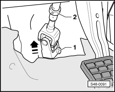
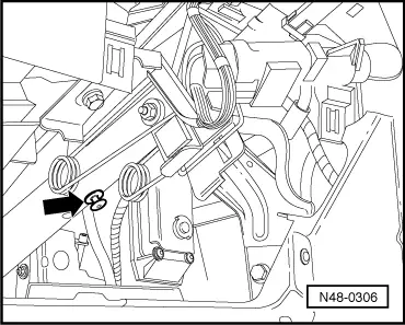
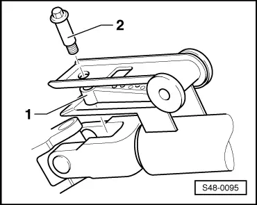
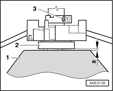
New steering columns supplied as spare parts are secured for transport. This transport security must be removed once the steering column has been installed.
t  The steering column is supplied as a spare part with ignition lock housing but without lock cylinder and ignition starter switch.
t  The ignition lock housing can be modified.
t  
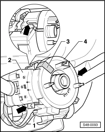
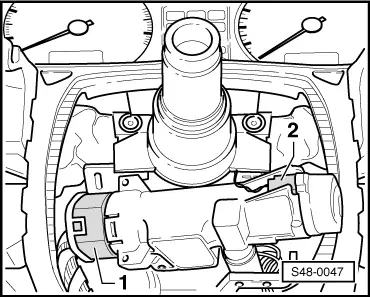
Remove and install ignition lock housing → Anchor.
t  It can happen that on new steering columns, which are supplied as spare parts, the lock cylinder and the ignition starter switch from the old steering column must be refitted or must be obtained as a spare part and installed → Electrical System; Rep. gr.94.
t  Repairing the steering column is not possible.
t  Replace the self-locking nuts and screws.
t  Welding and straightening of the steering components is not allowed.
t  Before disconnecting the battery determine the code of radio sets fitted with anti-theft coding.
t  After connecting the battery, perform the following:
–  on vehicles with radio encoding, carry out the coding,
–  set clock,
–  initialise power windows on vehicles fitted with power windows → BookletOctavia
Removing
–  Disconnect battery.
–  Put the wheels in straight-ahead position.
   
–  Release screws -2-.
–  Pull the footwell covering -1- out of the holders.
–  Remove the airbag on the driver's side → Body Work; Rep. gr.69.
–  Remove steering wheel → Body Work; Rep. gr.69.
–  Unclip cover for fuse carrier.
  S47-0061
–  Remove light switch -3- → Electrical System; Rep. gr.96.
–  Remove screws -5- for fuse carrier.
–  Screw out screws -1- and -2-.
–  Remove bottom part of dash panel -4-.
  S48-0078
–  Unscrew screws -1-, -2-, -3- and -4-.
–  Remove the top and bottom part of the steering column trim panel.
  S48-0187
The figure shows the coil spring -4- on a vehicle without Electronic Stability Program (ESP).
–  Secure the coil spring -4- against unintentional turning by covering it with adhesive tape -3-.
–  Unplug connector -1-.
–  Carefully remove all the plug connections from the steering column switch -2-.
-Arrows- Catch hook of coil spring -4-
  Note
t  The following working step is only required when replacing the coil spring or the steering column switch.
t  The coil spring must be removed and installed when it is in the centre position (wheel in straightahead position).
t  The coil spring is secured as a spare part in the centre position with a cable strap.
  S48-0093
–  Release catch hook -arrows- and remove coil spring -4- from steering column switch -2-.
  Note
If the coil spring remains on the steering column switch, ensure that the coil spring does not turn out of the centre position when placing down the steering column switch.
Vehicles with ESP
Vehicles with ESP are additionally fitted with the steering angle sender -G85-. It is fitted together with the coil spring in the housing.
The description of the basis, construction and function of the ESP can be found in self-study programme No. 28.
- Check whether the front wheels are in the straight-ahead position.
–  If necessary, fit on the steering wheel and put the front wheels in a straight ahead position.
–  Remove steering wheel.
  Note
The following two work steps must only be performed when reinstalling at a later stage the same housing with a coil spring.
  S48-0093
–  Position the steering angle sender in the centre position:
A yellow dot must be visible in the window -1-.
The markings -arrows- must be flush.
  S48-0189
–  Secure the coil spring -2- against unintentional turning by covering it with adhesive tape -1-. -3- Housing
  S48-0190
–  Disconnect plug -1- from housing.
–  Carefully release catch hooks -arrows- and remove housing -1- with steering angle sender -G85- and coil spring.
Continued for all vehicles
  S48-0191
–  Slacken the screw of the steering column switch -arrow- until the steering column switch can be slightly moved.
–  Remove steering column switch.
  N48-0305
–  Disconnect plugs -1- and -2-
LHD vehicles
  S48-0047
–  Unscrew plastic nuts -1- and remove cover -A-.
RHD vehicles
  S47-0026
–  Unscrew plastic screw -1-, remove plastic bushing, screw out plastic nut -2- and remove cover -A-.
Continued for all vehicles
  S47-0158
–  Release screw -1-.
02.97 ► if a clamping ring is installed.
–  Slacken the Allan screw of the clamping ring -2- so far until the universal joint can be removed from the steering gear pinion.
–  Remove the universal joint from the steering gear pinion -arrow-.
  Note
t  An assembly securing device is required to prevent the lower and the upper part of the steering column from separating during removal of the steering gear.
t  If the upper and the lower parts of the steering column are separated too widely or are pushed into one another then the gearing system will become separated. This could cause rattling noises during operation at a later stage if the gear teeth are no longer in their original installed position.
–  Secure the steering column before removal.
–  Push together or pull apart the steering column until the hole is visible.
  S48-0091
–  For example, fit a clip into the hole -arrow- in order to secure the position.
LHD vehicles
  N48-0306
–  Unscrew the self-locking nut -1- at the central pipe and pull out the screw -2-.
RHD vehicles
  S48-0089
–  Release the self-locking nut -2- and pull out the screw -1-.
Continued for all vehicles
  S48-0386
–  Release screws -arrows-.
–  Remove steering column.
  Note
t  New steering columns are generally supplied with ignition lock housings.
t  Ignition lock housings are supplied individually as a spare part.
Replace ignition lock housing
–  Remove ignition lock housing → Electrical System; Rep. gr.94.
  S48-0088
–  Bore out pull-off screws -arrows-.
–  Tighten pull-off screws -arrows- until the head shears off.
–  Install ignition lock housing → Electrical system; Rep. gr.94.
Install
  Note
t  New steering columns supplied as spare parts are secured for transport.
t  This transport security must be removed once the steering column has been installed.
t  It can happen that on new steering columns, which are supplied as spare parts, a new bushing and pull-off screw must be fitted before installing the steering column.
t  The pull-off screws and the bushing must be replaced after each disassembly of the bushing.
  S48-0094
–  Insert new bushing -1- and install pull-off screw -2-.
–  Tighten pull-off screw -2- until the head shears off.
LHD vehicles
  S48-0095
–  Position steering column to central pipe.
–  Screw in screws -3-, but do not tighten.
–  Insert new screw -2-.
–  Screw on new self-locking nut -1- and tighten to 10 Nm.
RHD vehicles
  S48-0090
–  Position steering column to central pipe.
–  Screw in screws -3-, but do not tighten.
–  Insert new screw -1-.
–  Screw on new self-locking nut -2- and tighten to 10 Nm.
Continued for all vehicles
–  Tighten screw -3- to 22 Nm.
–  Pull out transport security -arrow-.
  S48-0385
–  Slide the universal joint onto the steering pinion and tighten with new screw -1-.
02.97 ► if a clamping ring is installed.
–  Tighten the Allan screw of the clamping ring -2- to 17 Nm.
–  Fit cover for universal joint.
–  Mount plug for ignition starter lock and immobiliser.
–  Slide the steering column switch onto the steering column.
Vehicles without ESP
–  Slide the coil spring onto the steering column and lock into position with the steering column switch.
Vehicles with ESP
  S48-0096
–  Slide housing -1- with steering angle sender -G85- and coil spring onto the steering column and lock into position with steering column switch -arrows-.
–  Mount plug at housing -1-.
  Note
After removing the transport protection or the adhesive tape do not turn the coil spring, only the positioning of the steering angle sender -G85- in centre position is allowed.
  S48-0191
–  After installing a housing -1- remove transport protection -2-.
  S48-0192
–  After installing a used housing -3- remove adhesive tape -1-.
-2- Coil spring
  S48-0190
–  Position the steering angle sender -G85- in the centre position:
A yellow dot must be visible in the window -1-.
Markings -arrows- must be flush with each other.
Make sure this correct position is maintained.
The further work procedure is now valid again for all vehicles.
–  Fit the steering wheel onto the steering column and screw in the old internal serration screw and tighten.
  Note
  S48-0189
t  The fig. shows the steering column switch with coil spring -2- and steering wheel -1- on a vehicle without ESP.
t  On vehicles with ESP, the dimension „a“ between the coil spring integrated in the housing and the steering wheel is also 3 mm.
–  Align the steering column switch so that it is horizontal and set dimension „a“, subsequently tighten the clamping screw -3-.
–  Demount the steering wheel again.
  A48-0128
–  Mount plug -1-.
–  Fit together the plug connections on the steering column switch.
  Note
After removing the adhesive tape -3-, do not turn the coil spring out of its centre position.
–  Carefully remove the adhesive tape -3-.
–  Installing the trim panel for steering column switch → Body Work; Rep. gr.70.
–  Installing the lower part of the dash panel → Body Work; Rep. gr.70.
–  Install footwell covering on driver's side → Body Work; Rep. gr.68.
–  Install steering wheel → Body work; Rep. gr.69.
–  Install the airbag on the driver's side → Body Work; Rep. gr.69.
  WARNING
Nobody should be in the vehicle when the battery is being connected!
–  Connect battery → Electrical System; Rep. gr.27.
Vehicles without ESP:
–  Interrogate the fault memory → Chapter.
–  Erasing fault memory → Chapter.
Vehicles with ESP:
–  Perform the basic setting of the steering angle sender → Chapter.
–  Interrogate the fault memory → Chapter.
–  Erasing fault memory → Chapter.
  S48-0093

Removing and installing the ignition lock housing with the steering column mounted > < Check the steering column for damage