skoda Workshop Repair Guides

Skoda Workshop Service and Repair Manuals

Testing auxiliary signals > < Testing angle sender for throttle valve drive
Check accelerator pedal position sender
Special tools and workshop equipment required
t  Hand multimeter (e.g. -V.A.G 1526 A-)
t  Adapter cable set (e.g. -V.A.G 1594 A-)
t  Test box -V.A.G 1598/31-
t  Vehicle system tester -V.A.G 1552- with cable -V.A.G 1551/3-
The two accelerator pedal position senders - G79- and -G185- are located at the accelerator pedal and pass on the driver input to the engine control unit completely independently of each other (when accelerator is depressed). Both senders are located in a housing.
Test sequence
–  Connect the vehicle system tester -V.A.G 1552- and select control unit for engine electronics (address word 01); ignition switched on → Chapter.
   
If the following readout appears in the display:
–  Enter 08 for the function “Read measured value block” and confirm entry with the Q.
 
Vehicle system test                 HELP  
Select function XX
If the following readout appears in the display:
–  Enter 062 for the display group 062 and confirm entry with the Q key.
 
Reading measured value block
Enter display group number    XXX   
If the following readout appears in the display:
–  Test the specified values for the electronic throttle potentiometer voltages.
  Note
The engine control unit converts the voltage values of the accelerator pedal position sender in percentage (in relation to 5 Volts). 5 Volts power supply correspond to 100 %.
–  Observe display fields 3 and 4.
–  Slowly press the accelerator pedal fully down.
The percentage indication in display field 3 must rise gradually. The tolerance range 12…97 % is not fully used up.
The percentage indication in display field 4 must rise gradually. The tolerance range 4…49 % is not fully used up.
  Note
The value displayed in display field 3 must always be approximately double the value in display field 4.
If the display does not occur as described:
–  Check the voltage supply and the wiring of the accelerator pedal position sender → Anchor.
Check the voltage supply of the accelerator pedal position sender
–  Remove the bottom part of the dash panel → Body Work → Rep. Gr.70.
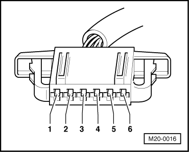
–  Separate plug connection for accelerator pedal position sender.
–  Switch on ignition.
 
Reading measured value block  62   ->
15,0 %     75,0 %     15,0 %     7,0 %  
–  Connect multimeter for voltage measurement in the following manner:
  M20-0016
Contact to connector plugSpecification 
1 + earthapprox. 5 V 
1 + 5approx. 5 V
2 + earthapprox. 5 V
2 + 3approx. 5 V

If the specified values are reached:
–  Also check the signal lines.
If the specified values are not reached:
–  Test the wiring from the engine control unit to the accelerator pedal position senders → Anchor.
Check cables
–  Connect → Chaptertest box -V.A.G 1598/31- to the wiring loom of the engine control unit.
–  Check the following wires for interruption or short-circuit to earth or positive:
   
Contact to connector plugTest box -V.A.G 1598/31-, bush 
119 
218
350
451
545
664


Testing auxiliary signals > < Testing angle sender for throttle valve drive